


TVS600 & TVS600A Command Reference
2–121
INPut Subsystem
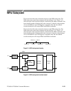
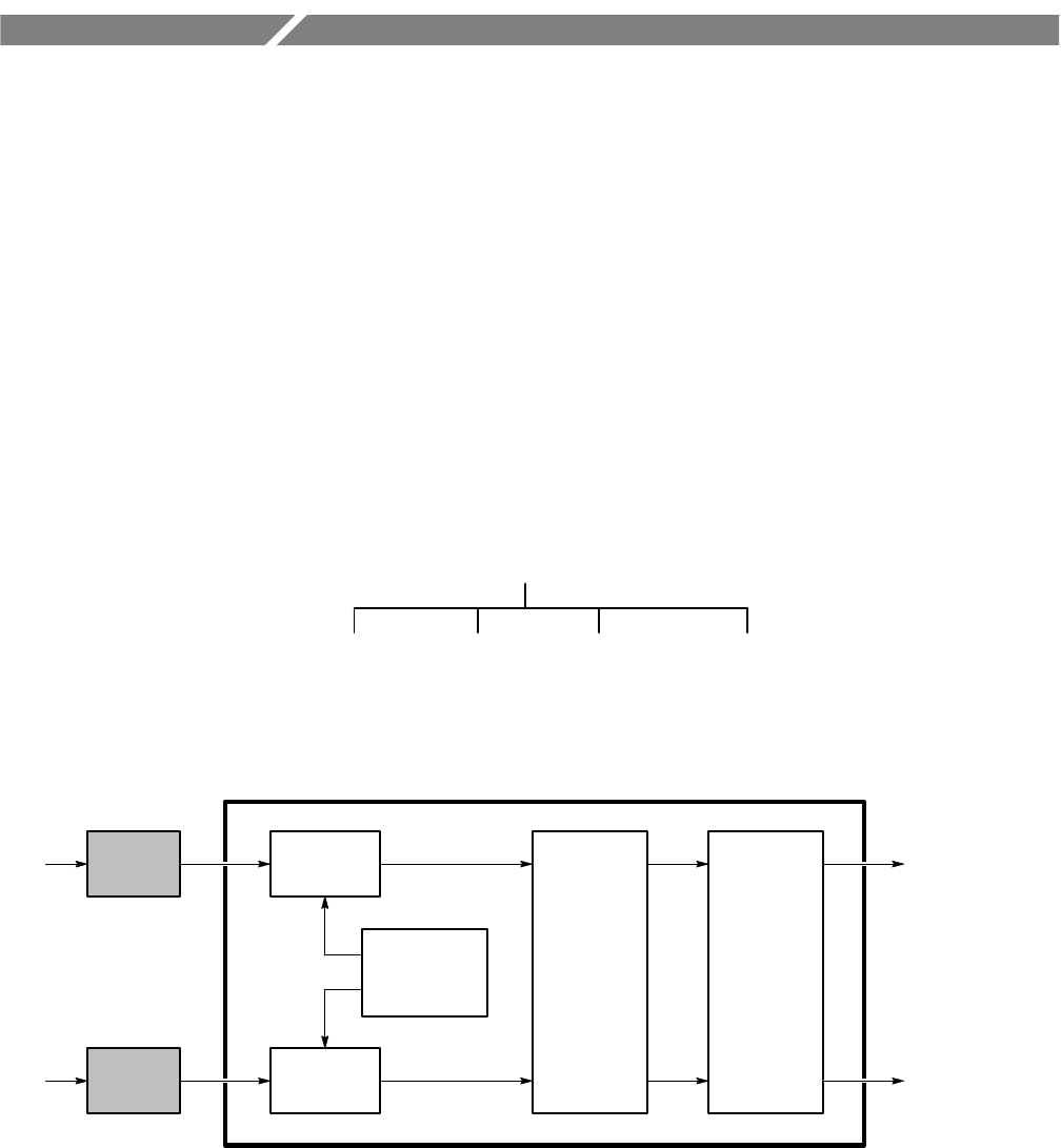
This section describes each command and query in the INPut subsystem. The
INPut subsystem controls the parameters shown in Figure 2–14. Figure 2–15
shows the part of the waveform analyzer controlled by the INPut commands. The
input channel number, defined at the probe connector, is shared as the parameter
<n> for the INPut<n> and VOLTage<n> commands. Only the four-channel
waveform analyzers will accept INPut3 and INPut4 commands.
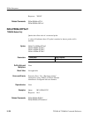
INPut[1] | INPut2
:IMPedance:COUPling :FILTer :PROTection
Figure 2–14: INPut subsystem hierarchy
:FUNCtion
:DATA
:AVERage
:AADVance
:SWEep
:ROSCillator
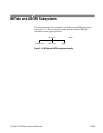
INPut[1]
SENSe
:VOLTage[1]
INPut2 :VOLTage2
CH 1
CH 2
Figure 2–15: INPut subsystem functional model