


Appendix C: Algorithms
C–24
TVS600 & TVS600A Command Reference
b = 1
b = 5
b = 20
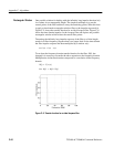
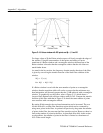
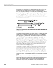
Figure C–10: Kaiser window with 200 points and b = 1, 5 and 20
For larger values of b, the Kaiser window tapers off slowly towards the edges of
the window. Using the same number of data points and taking a Fourier
transform of a Kaiser window and a rectangular window, the transform of the
Kaiser window is broader than the rectangular window but the side lobes are
much farther down.
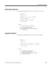
As stated in the last section, the frequency domain transfer function of the filter
is given by convolving the transfer function of the ideal filter with that of the
window.
W(f) + T
{
w(t)
}
New H(f) + H(f)*W(f)
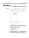
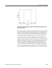
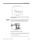
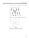
If a Kaiser window is used with the same number of points as a rectangular
window, then the transition width will not be as narrow but the minimum stop
band attenuation will be much greater than the 21 dB achieved with a rectangular
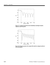
window. To graphically see this effect, refer to Figure C–11 which shows a
lowpass filter obtained with a Kaiser window with b=2.65. Compare the transfer
function of this filter with that in Figure C–9 where the same number of points
were used but with a rectangular window.
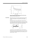
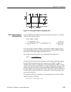
By setting b high enough, the stop band attenuation can be increased. The cost
for this increase is a wider filter transition region which can be countered by
using more points in the filter. As pointed out previously, the greater the number
of points in the filter, the narrower the filter transition region. However, there is a
limit to the number of points in the filter. As described more fully in the section
on edge effects, the number of points in the filter is limited to a maximum of
10% of the record length.