


Appendix C: Algorithms
C–30
TVS600 & TVS600A Command Reference
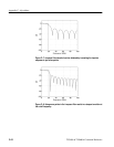
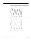
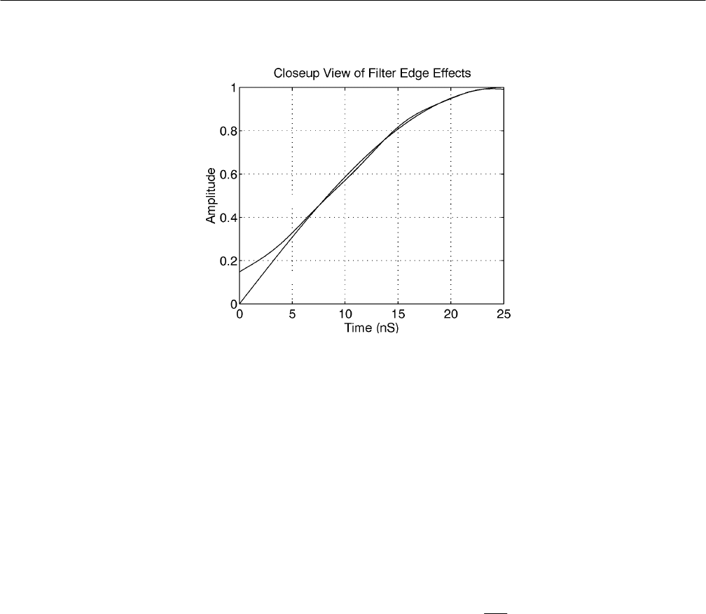
Source Signal
Filtered Data
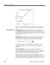
Figure C–17: View of the filtered record showing the first 5% of the filtered data
Stop Band Attenuation. The stop band attenuation, or stop band rejection, is set
by the SREJ parameter. The attenuation in the stop band is at least the value
given by SREJ. Typically the minimum attenuation occurs at the start of the stop
band. Further into the stop band the attenuation is typically several to tens of dB
greater than SREJ.
Pass Band Ripple. The ripple in the pass band is not explicitly set through the
filter commands. For the Kaiser window algorithm used in the waveform
analyzer the pass band ripple is directly related to the stop band attenuation:
PassBand Ripple (dB) + 20log
10
ƪ
1 ) 10
–SREJ
20
ƫ
For example, if the SREJ is set to 40dB then the pass band ripple will be less
than 0.0864 dB; if SREJ is set to 60dB, pass band ripple will be less than
0.00868 dB.
Filter Cutoff and Roll Off. The digital filters implemented in the waveform
analyzer are different than traditional analog filters. One important distinction is
that the STAR, STOP, LPAS, and HPAS frequencies are not the –3 dB cutoff
frequencies for the filter but are instead –6 dB cutoff frequencies.
Analog filter designers often characterize filters by the roll off rate beyond a
cutoff frequency. For example, analog filters are characterized with a roll off of
20 dB/decade, 40 dB/decade, etc. Unfortunately, these familiar analog terms do
not apply to digital filters. Unlike analog filters, digital filters do not continue to
Filter Performance