


Interrupts
5-23
Program Control
For ’C2xx devices other than the ’C209, Figure 5–8 shows the IMR. Descrip-
tions of the bits follow the figure. For a description of the ’C209 IMR, see sub-
section 11.3.1,
’C209 Interrupt Registers
, on page 11-11.
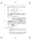
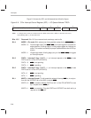
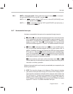
Figure 5–8. ’C2xx Interrupt Mask Register (IMR) — Data-Memory Address 0004h
15 6
5 4 3 2 1 0
Reserved TXRXINT XINT RINT TINT INT2/INT3 HOLD/INT1
0 R/W–0 R/W–0 R/W–0 R/W–0 R/W–0 R/W–0
Note: 0 = Always read as zeros; R = Read access; W = Write access; value following dash (–) is value after reset.
Bits 15–6 Reserved. Bits 15–6 are reserved and are always read as 0s.
Bit 5 TXRXINT — Transmit/receive interrupt mask. Bit 5 is tied to the transmit/receive in-
terrupt for the asynchronous serial port.
TXRXINT = 0 Interrupt TXRXINT is masked.
TXRXINT = 1 Interrupt TXRXINT is unmasked.
Bit 4 XINT — Transmit interrupt mask. Bit 4 is tied to the transmit interrupt for the synchro-
nous serial port.
XINT = 0 Interrupt XINT is masked.
XINT = 1 Interrupt XINT is unmasked.
Bit 3 RINT — Receive interrupt mask. Bit 3 is tied to the receive interrupt for the synchro-
nous serial port.
RINT = 0 Interrupt RINT is masked.
RINT = 1 Interrupt RINT is unmasked.
Bit 2 TINT — Timer interrupt mask. Bit 2 is tied to the interrupt for the timer.
TINT = 0 Interrupt TINT is masked.
TINT = 1 Interrupt TINT is unmasked.
Bit 1 INT2/INT3 — Interrupt 2/Interrupt 3 mask. The INT2
pin and the INT3 pin are both
tied to bit 1. With this bit, you mask both INT2
and INT3 simultaneously. In conjunction
with this bit, bits MINT2 and MINT3 of the ICR are used to individually unmask INT2
and INT3.
INT2/INT3 = 0 INT2
and INT3 are masked.
INT2/INT3 = 1 If INT2/INT3 = 1 and MINT2 = 1, INT2
is unmasked.
If INT2/INT3 = 1 and MINT3 = 1, INT3
is unmasked.