


Indirect Addressing Mode
6-12
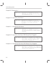
Example 6–6. Selecting a New Current Auxiliary Register
MAR*,AR1 ;Load the ARP with 1 to make AR1 the
;current auxiliary register.
LT *+,AR2 ;AR2 is the next auxiliary register.
;Load the TREG with the content of the
;address referenced by AR1, add one to
;the content of AR1, then make AR2 the
;current auxiliary register.
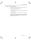
MPY* ;Multiply TREG by content of address
;referenced by AR2.
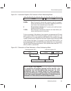
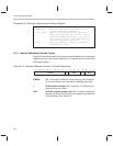
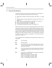
6.3.4 Indirect Addressing Opcode Format
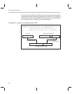
Figure 6–6 shows the format of the instruction word loaded into the instruction
register when you use indirect addressing. The opcode fields are described
following the figure.
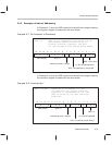
Figure 6–6. Instruction Register Content in Indirect Addressing
0123456789101112131415
NARNARU1
8 MSBs
8 MSBs Bits 15 through 8 indicate the instruction type (for example,
LT) and also contain any information regarding data shifts.
1 Direct/indirect indicator. Bit 7 contains a 1 to define the ad-
dressing mode as indirect.
ARU Auxiliary register update code. Bits 6 through 4 determine
whether and how the current auxiliary register is incremented
or decremented. See Table 6–2.