


How To Use the Instruction Descriptions
7-14
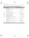
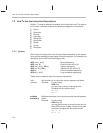
7.2.2 Operands
Operands can be constants, or assembly-time expressions referring to
memory, I/O ports, register addresses, pointers, shift counts, and a variety of
other constants. The operands category for each instruction description de-
fines the variables used for and/or within operands in the syntax expressions.
For example, for the ADD instruction, the syntax category gives these syntax
expressions:
ADD
dma
[,
shift
] Direct addressing
ADD
dma
, 16 Direct with left shift of 16
ADD
ind
[,
shift
[, AR
n
]] Indirect addressing
ADD
ind
, 16 [, AR
n
] Indirect with left shift of 16
ADD #
k
Short immediate addressing
ADD #
lk
[,
shift
] Long immediate addressing
The operands category defines the variables
dma
,
shift
,
ind
,
n
,
k
, and
lk
. For
ind
, an indirect addressing variable, you supply one of the following seven
symbols:
* *+ *– *0+ *0– *BR0+ *BR0–
These symbols are defined in subsection 6.3.2,
Indirect Addressing Options
,
on page 6-9.
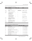
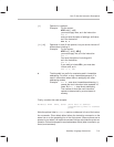
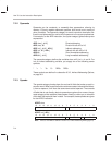
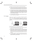
7.2.3 Opcode
The opcode category breaks down the various bit fields that make up each in-
struction word. When one of the fields contains a constant value derived direct-
ly from an operand, it will have the same name as that operand. The contents
of fields that do not directly relate to operands are given other names; the op-
code category either explains these names directly or refers you to a section
of this book that explains them in detail. For example, these opcodes are given
for the ADDC instruction:
ADDC
dma
1514131211109876543210
0
11000000 dma
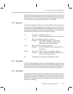
ADDC
ind
[, AR
n
]
1514131211109876543210
0
11000001 ARU N NAR
Note: ARU, N, and NAR are defined in Section 6.3,
Indirect Addressing Mode
(page 6-9).