


Components and Basic Operation
10-6
10.2.5 Basic Operation
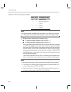
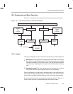
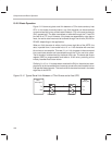
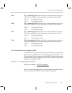
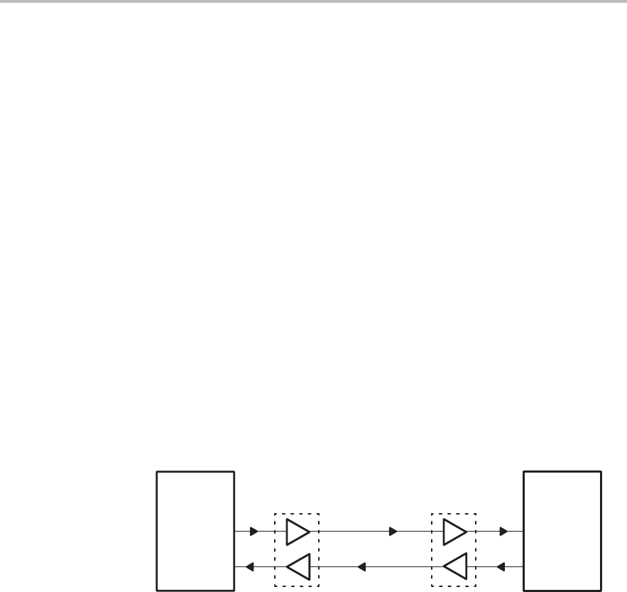
Figure 10–2 shows a typical serial link between a ’C2xx device and any host
CPU. In this mode of communication, any 8-bit character can be transmitted
or received serially by way of the transmit data pin (TX) or the receive data pin
(RX), respectively. The data transmitted or received through the TX and RX
pins will be at TTL level. However, if the hosts are separated by a few feet or
more, the serial data lines must be buffered through line-drivers (RS-232 or
RS-485, depending on the application).
When an 8-bit character is written into the lower eight bits of the ADTR, the
data, in parallel form, is converted into a 10- or 11-bit character with one start
bit and one or two stop bits. This new 10- or 11-bit character is then converted
into a serial data stream and transmitted through the TX pin one bit at a time.
The bit duration is determined by the baud clock rate. The baud-rate divisor
register (BRD) is programmable and takes a 16-bit value, providing all the
industry-standard baud rate values.
Similarly, if a 10- or 11-bit data stream reaches the RX pin, the serial port sam-
ples the bit at the transmitted baud rate and converts the serial stream into an
8-bit parallel data character. The received 8-bit character is stored in the lower
eight bits of the ADTR.
Figure 10–2. Typical Serial Link Between a ’C2xx Device and a Host CPU
’C2xx
TX
RX
Host
RX
TX
Line drivers Line drivers
serial port
serial port