Controlling and Resetting the Port
10-7
Asynchronous Serial Port
10.3 Controlling and Resetting the Port
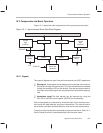
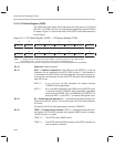
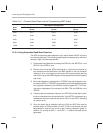
The asynchronous serial port is programmed through three on-chip registers
mapped to I/O space: the asynchronous serial port control register (ASPCR),
the I/O status register (IOSR), and the baud-rate divisor register (BRD). This
section describes the contents of each of these registers and also explains the
use of associated control features.
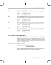
10.3.1 Asynchronous Serial Port Control Register (ASPCR)
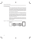
The ASPCR controls the operation of the asynchronous serial port.
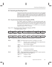
Figure 10–3 shows the fields in the 16-bit memory-mapped ASPCR and bit
descriptions follow the figure. All of the bits in the register are read/write, with
the exception of the reserved bits (12–10). The ASPCR is an on-chip register
mapped to address FFF5h in I/O space.
Figure 10–3. Asynchronous Serial Port Control Register (ASPCR)
— I/O-Space Address FFF5h
15 14 13 12 11 10 9 8
FREE SOFT URST Reserved DIM TIM
R/W–0 R/W–0 R/W–0 0 R/W–0 R/W–0
7 6 5 4 3 2 1 0
RIM STB CAD SETBRK CIO3 CIO2 CIO1 CIO0
R/W–0 R/W–0 R/W–0 R/W–0 R/W–0 R/W–0 R/W–0 R/W–0
Note: 0 = Always as zeros; R=Read access; W=Write access; value following dash (–) is value after reset.
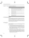
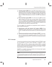
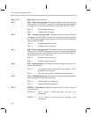
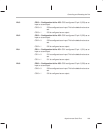
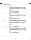
Bit 15 FREE. This bit sets the port to function in emulation or run mode.
FREE = 0 Emulation mode is selected. SOFT then determines the
which emulation mode is enabled.
FREE = 1 Free run mode is selected.
Bit 14 SOFT. This bit is enabled when the FREE bit is 0. It determines the emulation
mode.
SOFT = 0 Process stops immediately.
SOFT = 1 Process stops after word completion.
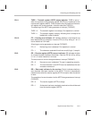
Bit 13 URST — Reset asynchronous serial port bit. URST is used to reset the
asynchronous serial port. At reset, URST = 0.
URST = 0 The port is in reset.
URST = 1 The port is enabled.


