


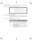

Instruction Set Summary
7-3
Assembly Language Instructions
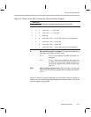
IAAA AAAA (One I followed by seven As) The I at the left represents a bit
that reflects whether direct addressing (I = 0) or indirect ad-
dressing (I = 1) is being used. When direct addressing is used,
the seven As are the seven least significant bits (LSBs) of a
data memory address. For indirect addressing, the seven As
are bits that control auxiliary register manipulation (see Sec-
tion 6.3,
Indirect Addressing Mode
, p. 6-9).
IIII IIII (Eight Is) An 8-bit constant used in short immediate addres-
sing
I IIII IIII (Nine Is) A 9-bit constant used in short immediate addressing
for the LDP instruction
I IIII IIII IIII (Thirteen Is) A 13-bit constant used in short immediate ad-
dressing for the MPY instruction
I NTR# A 5-bit value representing a number from 0 to 31. The INTR
instruction uses this number to change program control to one
of the 32 interrupt vector addresses.
PM A 2-bit value copied into the PM bits of status register ST1 by
the SPM instruction
SHF A 3-bit left-shift value
SHFT A 4-bit left-shift value
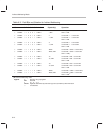
TP A 2-bit value used by the conditional execution instructions to
represent four conditions:
BIO
pin low TP = 00
TC bit =1 TP = 01
TC bit = 0 TP = 10
No condition TP = 11