


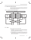
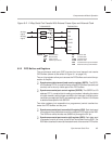

Controlling and Resetting the Port
9-10
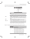
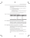
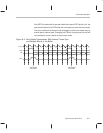
Bits 9–8 FR1, FR0 — FIFO receive-interrupt bits. The values you write to FR0 and
FR1 set an interrupt trigger condition based on the contents of the receive
FIFO buffer. When this condition is met, a receive interrupt (RINT) is gener-
ated and the data can be transferred in from the FIFO buffer using the IN
instruction. Table 9–4 lists the possible trigger conditions.
Table 9–4. Controlling Receive Interrupt Generation by Writing to Bits FR1 and FR0
Select Bits
FR1 FR0 Generate RINT when...
0 0 Receive FIFO buffer is not empty.
0 1 Receive FIFO buffer holds at least two words.
1 0 Receive FIFO buffer holds at least three words.
1 1 Receive FIFO buffer is full (holds four words).
Bit 7 OVF — Overflow bit. This bit is set whenever the receive FIFO buffer is full
and another word is received in the RSR. The contents of the FIFO buffer
will not be overwritten by this new word. OVF is cleared when the FIFO buffer
is read.
Bit 6 IN0 — Input bit. This bit allows the CLKR pin to be used as a bit input. IN0
reflects the current logic level on the CLKR pin. IN0 can be tested by using
a BIT or BITT instruction on the SSPCR. If the serial port is not used, IN0 can
be used as a general-purpose bit input.
Bit 5 XRST — Transmit reset bit. This bit resets the transmitter portion of the se-
rial interface. Set XRST to 0 to put the transmitter in reset. Set XRST to 1 to
bring the transmitter out of reset.
Bit 4 RRST — Receive reset bit. This bit resets the receiver portion of the serial
interface. Set RRST to 0 to put the receiver in reset. Set RRST to 1 to bring
the receiver out of reset.