


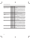
Instruction Set Comparison Table
B-34
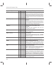
Syntax
Description5x2xx2x1x
SUBT
dma
SUBT {
ind
} [
, next ARP
]
√
√
√
√
√
√
Subtract From Accumulator With Shift Specified
by T Register
Left shift the data-memory value as specified by the 4
LSBs of the T register (TMS320C2x/2xx) or TREG1
(TMS320C5x), and subtract the result from the accu-
mulator. If a shift is specified, left shift the data-memory
value before subtracting. During shifting, low-order
bits are zero filled, and high-order bits are sign ex-
tended if SXM = 1.
SXF
√ √ √
Set External Flag
Set the XF pin and the XF status bit to 1.
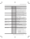
TBLR
dma
TBLR {
ind
} [
, next ARP
]
√
√
√
√
√
√
√
√
Table Read
Transfer a word from program memory to a data-
memory location. The program-memory address is in
the 12 (TMS320C1x) or 16 (TMS320C2x/2xx/5x)
LSBs of the accumulator.
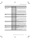
TBLW
dma
TBLW {
ind
} [
, next ARP
]
√
√
√
√
√
√
√
√
Table Write
Transfer a word from data-memory to a program-
memory location. The program-memory address is in
the 12 (TMS320C1x) or 16 (TMS320C2x/2xx/5x)
LSBs of the accumulator.
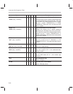
TRAP
√ √ √
Software Interrupt
The TRAP instruction is a software interrupt that trans-
fers program control to program-memory address 30h
(TMS320C2x) or 22h (TMS320C2xx/5x) and pushes
the PC + 1 onto the hardware stack. The instruction at
address 30h or 22h may contain a branch instruction
to transfer control to the TRAP routine. Putting the PC
+ 1 on the stack enables an RET instruction to pop the
return PC.
XC
n, cond
1
[
, cond
2
] [, ...]
√
Execute Conditionally
Execute conditionally the next
n
instruction words
where 1
≤
n
≤ 2. Not all combinations of conditions are
meaningful.