


Direct Addressing Mode
6-5
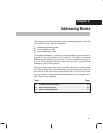
Addressing Modes
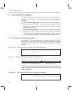
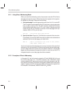
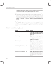
Figure 6–4. Instruction Register (IR) Contents in Direct Addressing Mode
0123456789101112131415
7 LSBs0
8 MSBs
8 MSBs Bits 15 through 8 indicate the instruction type (for example,
ADD) and also contain any information regarding a shift of the
data value to be accessed by the instruction.
0 Direct/indirect indicator. Bit 7 contains a 0 to define the ad-
dressing mode as direct.
7 LSBs Bits 6 through 0 indicate the offset for the data-memory ad-
dress referenced by the instruction.
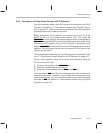
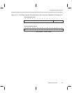
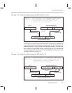
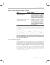
To form a complete 16-bit address, the processor concatenates the DP value
and the seven LSBs of the instruction register, as shown in Figure 6–5. The
DP supplies the nine most significant bits (MSBs) of the address (the page
number), and the seven LSBs of the instruction register supply the seven LSBs
of the address (the offset). For example, to access data address 003Fh, you
specify data page 0 (DP = 0000 0000 0) and an offset of 011 1111. Concatenat-
ing the DP and the offset produces the 16-bit address 0000 0000 0011 1111,
which is 003Fh or decimal 63.
Figure 6–5. Generation of Data Addresses in Direct Addressing Mode
7 LSBs from IR
16-bit data-memory address
All 9 bits from DP
Data page pointer (DP)
Page (9 MSBs) Offset (7 LSBs)
Instruction register (IR)
8 MSBs 7 LSBs9 bits 0
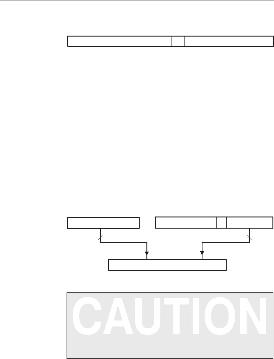
Initialize the DP in All Programs
It is critical that all programs initialize the DP. The DP is not
initialized by reset and is undefined after power up. The ’C2xx
development tools use default values for many parameters,
including the DP. However, programs that do not explicitly initialize
the DP can execute improperly, depending on whether they are
executed on a ’C2xx device or with a development tool.