


Power-Down Mode
5-37
Program Control
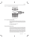
5.8.2 Termination of Power-Down During a HOLD Operation
One of the necessary steps in the HOLD operation is the execution of an IDLE
instruction (see Section 4.7,
Direct Memory Access Using The HOLD Opera-
tion
, on page 4-27) . There are unique characteristics of the HOLD operation
that affect how the IDLE state can be exited.
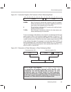
Before performing a HOLD operation, your program must write a 0 to the
MODE bit (bit 4 of the interrupt control register, ICR). This makes the
HOLD
/INT1 pin both negative- and positive-edge sensitive. A
falling
edge on
HOLD
/INT1 will cause the CPU to branch to the interrupt service routine, which
initiates the HOLD operation with an IDLE instruction. A subsequent
rising
edge on HOLD/INT1 can take the CPU out of the IDLE state and end the HOLD
operation. This rising-edge interrupt does
not
cause the CPU to branch to the
interrupt service routine.
The recommended software logic for the HOLD operation is described in Sec-
tion 4.7,
Direct Memory Access Using the HOLD Operation
, on page 4-27.
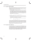
During a HOLD operation, there are only three valid methods for taking the
CPU out of the IDLE state:
Causing a rising edge on the HOLD/INT1 pin.
Asserting a system reset at the reset pin.
Asserting the nonmaskable interrupt NMI at the NMI pin.
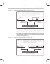
If you use reset or NMI
, the CPU will immediately execute the corresponding
interrupt service routine. In addition, if you use reset, the contents of some reg-
isters will be changed. For more information about exiting a HOLD operation
with reset or NMI
, see Section 4.7,
Direct Memory Access Using The HOLD
Operation
, on page 4-27.