


TBLR
Table Read
7-186
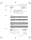
Syntax TBLR
dma
Direct addressing
TBLR
ind
[, AR
n
] Indirect addressing
Operands dma: 7 LSBs of the data-memory address
n: Value from 0 to 7 designating the next auxiliary register
ind: Select one of the following seven options:
* *+ *– *0+ *0– *BR0+ *BR0–
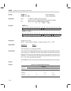
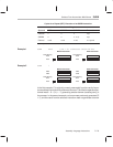
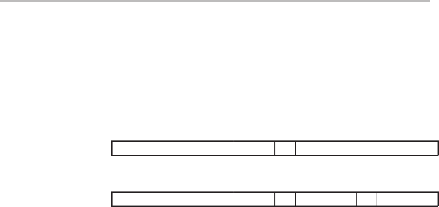
TBLR
dma
1514131211109876543210
1
01001100 dma
TBLR
ind
[, AR
n
]
1514131211109876543210
1
01001101 ARU N NAR
Note: ARU, N, and NAR are defined in Section 6.3,
Indirect Addressing Mode
(page 6-9).
Execution Increment PC, then ...
(PC) → MSTACK
(ACC(15:0)) → PC
(pma) → data-memory address
For indirect, modify (current AR) and (ARP) as specified,
(PC) + 1 → PC
While (repeat counter) ≠ 0
(pma) → data-memory address
For indirect, modify (current AR) and (ARP) as specified,
(PC) + 1 → PC
(repeat counter) –1 → repeat counter.
(MSTACK) → PC
Status Bits None
Description The TBLR instruction transfers a word from a location in program memory to
a data-memory location specified by the instruction. The program-memory ad-
dress is defined by the low-order 16 bits of the accumulator. For this operation,
a read from program memory is performed, followed by a write to data memory.
When repeated with the repeat (RPT) instruction, TBLR effectively becomes
a single-cycle instruction, and the program counter that was loaded with
(ACC(15:0)) is incremented once each cycle.
Words 1
Opcode