


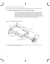
Connections Between the Emulator and the Target System
E-10
E.6 Connections Between the Emulator and the Target System
It is extremely important to provide high-quality signals between the emulator
and the JTAG target system. You must supply the correct signal buffering, test
clock inputs, and multiple processor interconnections to ensure proper emula-
tor and target system operation.
Signals applied to the EMU0 and EMU1 pins on the JTAG target device can
be either input or output. In general, these two pins are used as both input and
output in multiprocessor systems to handle global run/stop operations. EMU0
and EMU1 signals are applied only as inputs to the XDS510 emulator header.
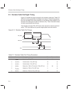
E.6.1 Buffering Signals
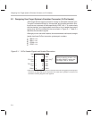
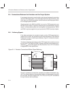
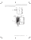
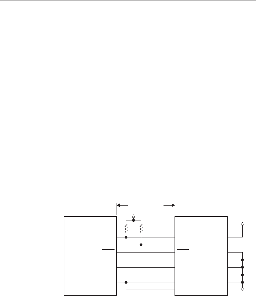
If the distance between the emulation header and the JTAG target device is
greater than 6 inches, the emulation signals must be buffered. If the distance
is less than 6 inches, no buffering is necessary. Figure E–4 shows the simpler,
no-buffering situation.
The distance between the header and the JTAG target device must be no more
than 6 inches. The EMU0 and EMU1 signals must have pullup resistors con-
nected to V
CC
to provide a signal rise time of less than 10 µs. A 4.7-kΩ resistor
is suggested for most applications.
Figure E–4. Emulator Connections Without Signal Buffering
V
CC
Emulator header
V
CC
GND
12
10
8
6
4
5
GND
GND
GND
GND
GND
PD
TCK_RET
TCK
TDO
TDI
TMS
TRST
EMU1
EMU0
9
11
7
3
1
2
14
13
JTAG device
TCK
TDO
TDI
TMS
TRST
EMU1
EMU0
6 inches or less
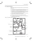
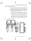
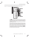
Figure E–5 shows the connections necessary for buffered transmission sig-
nals. The distance between the emulation header and the processor is greater
than 6 inches. Emulation signals TMS, TDI, TDO, and TCK_RET are buffered
through the same device package.