


Boot Loader
4-17
Memory and I/O Spaces
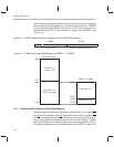
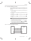
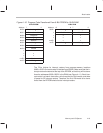
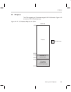
Figure 4–9 shows how to store a 16-bit program into the 8-bit EPROM. A sub-
script h (for example, on Word1
h
) indicates the high-byte and a subscript l (for
example, on Word1
l
) indicates the low byte.
Figure 4–9. Storing the Program in the EPROM
16-Bit Program 8-Bit EPROM
15 8 7 0 Address 7 0
Word1
h
Word1
l
8000h Destination
h
Word2
h
Word2
l
8001h Destination
l
•. • 8002h Length N
h
• • 8003h Length N
l
• • 8004h Word1
h
Wordn
h
Wordn
l
8005h Word1
l
8006h Word2
h
8007h Word2
l
••
••
••
nnnEh Wordn
h
nnnFh Wordn
l
4.5.4 Enabling the Boot Loader
To enable the boot loader, tie the BOOT pin low and reset the device. The
BOOT
pin is sampled only at reset. If you don’t want to use the boot loader,
tie BOOT
high before initiating a reset.
Three main conditions occur at reset that ensure proper operation of the boot
loader:
All maskable interrupts are globally disabled (INTM bit = 1).
On-chip DARAM block B0 is mapped to data space (CNF bit = 0).
Seven wait states are selected for program and data spaces.
After a hardware reset, the processor either executes the boot loader software
or skips execution of the boot loader, depending on the level on the BOOT
pin:
If BOOT is low, the processor branches to the location of the on-chip boot
loader program.
If BOOT is high, the processor begins program execution at the address
pointed to by the reset vector at address 0000h in program memory.