


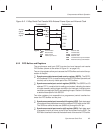

Controlling and Resetting the Port
9-11
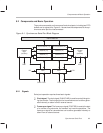
Synchronous Serial Port
Bit 3 TXM — Transmit mode. This bit determines the source device for the frame
synchronization (frame sync) pulse for transmissions. It configures the
transmit frame sync pin (FSX) as an output or as in input. Note that the
receive frame sync pin (FSR) is always configured as an input.
TXM = 0 An external frame sync source is selected. FSX is configured
as an input and accepts an external frame sync signal. The
transmitter idles until a frame sync pulse is supplied on the
FSX pin.
TXM = 1 The internal frame sync source is selected. The FSX pin is
configured as an output and sends a frame sync pulse at the
beginning of every transmission. In this mode, frame sync
pulses are generated internally when data is transferred from
the SDTR to the XSR to initiate data transfers. The internally
generated framing signal is synchronous with respect to
CLKX.
Bit 2 MCM — Clock mode. This bit determines the source device for the clock
for a serial port transfer. It configures the clock transmit pin (CLKX) as an out-
put or as an input. Note that the clock receive pin (CLKR) is always config-
ured as an input.
MCM = 0 An external clock source is selected. The CLKX pin is config-
ured as an input that accepts an external clock signal.
MCM = 1 The internal clock source is selected. The CLKX pin is config-
ured as an output driven by an internal clock source with a fre-
quency equal to 1/2 that of CLKOUT1. Note that if MCM = 1
and DLB = 1, CLKR is also supplied by the internal source.
Bit 1 FSM — Frame synchronization mode. The FSM bit specifies whether
frame synchronization pulses are required between consecutive word trans-
fers.
FSM = 0 Continuous mode is selected. In continuous mode, one frame
sync pulse (FSX/FSR) initiates the transmission/reception of
multiple words.
FSM = 1 Burst mode is selected. A frame sync pulse (FSX/FSR) is re-
quired for the transmission/reception of each word.