Register Descriptions
A-8
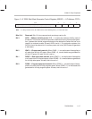
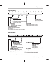
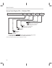
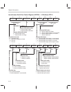
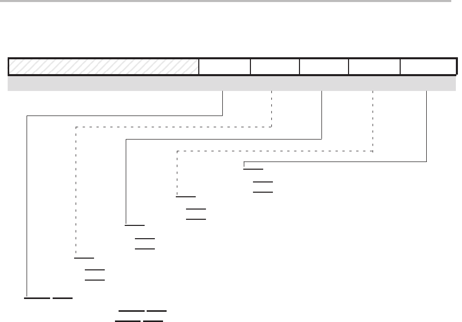
Interrupt Control Register (ICR) — I/O Address FFECh
15 5 4 3 2 1 0
0 0 0 0 0 0
Reserved
†
MODE FINT3 FINT2 MINT3 MINT2
INT3 request will not reach CPU.
INT3
request will reach CPU.
0
1
Double-edge mode.
HOLD/INT1 pin both negative- and positive-edge sensitive
Single-edge mode.
HOLD/INT1 pin only negative-edge sensitive
0
1
INT3
not pending
INT3 pending
0
1
INT2
not pending
INT2 pending
0
1
0
1
INT2
request will not reach CPU.
INT2 request will reach CPU.
R/W R/W1C R/W1C R/W R/W
HOLD/INT1 pin mode
INT3 flag
INT2
flag
INT3
mask
INT2
mask
†
These reserved bits are always read as 0s. Writes have no effect.


