


Direct Addressing Mode
6-7
Addressing Modes
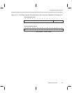
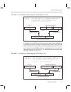
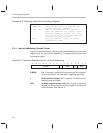
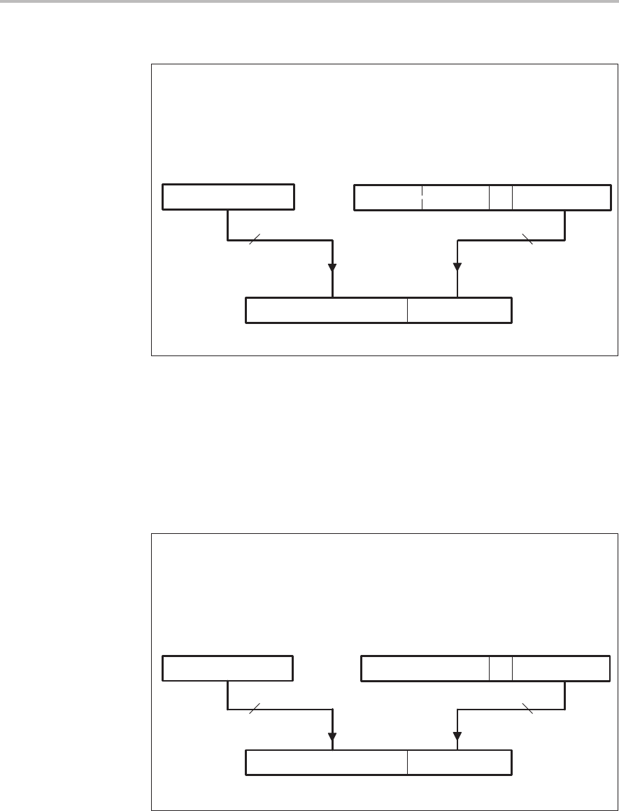
Example 6–3. Using Direct Addressing with ADD (Shift of 0 to 15)
LDP #4 ;Set data page to 4 (addresses 0200h–027Fh).
ADD 9h,5 ;The contents of data address 0209h are
;left–shifted 5 bits and added to the
;contents of the accumulator.
7 LSBs from IR
16-bit data address 0209h
All 9 bits from DP
DP = 4 Instruction register (IR)
0 0 1 0
0 0 0 1 0 0 1
0 0 0 0 0 0 1 0 0 0
0 0 1 0
ADD
opcode
Shift of 5
0 0 0 0 0 0 1 0 0
0 0 0 1 0 0 1
9h
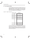
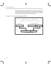
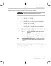
In Example 6–4, the ADD instruction references a data memory address that
is generated as shown following the program code. For any instruction that
performs a shift of 16, the shift value is not embedded directly in the instruction
word; instead, all eight MSBs contain an opcode that not only indicates the
instruction type but also a shift of 16. The eight MSBs of the instruction word
indicate an ADD with a shift of 16.
Example 6–4. Using Direct Addressing with ADD (Shift of 16)
LDP #5 ;Set data page to 5 (addresses 0280h–02FFh).
ADD 9h,16 ;The contents of data address 0289h are
;left–shifted 16 bits and added to the
;contents of the accumulator.
7 LSBs from IR
16-bit data address 0289h
All 9 bits from DP
DP = 5 Instruction register (IR)
0 0 0 1 0 0 10 0 0 0 0 0 1 0 1 0
ADD with shift of 16
opcode
0 0 0 0 0 0 1 0 1
0 0 0 1 0 0 1
9h
0 1 1 0 0 0 0 1