General-Purpose I/O Pins
8-18
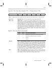
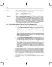
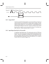
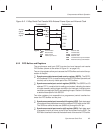
Figure 8–7. BIO Timing Diagram Example
BIO
CLKOUT1
1 CLKOUT1
cycle
8.6.2 Output Pin XF
The XF pin is the external flag output pin. If you connect XF to an input pin of
another processor, you can use XF as a signal to other processor. The most
recent XF value is latched in the ’C2xx, and that value is indicated by the XF
status bit of status register ST1. You can set XF (XF = 1) with the SETC XF (set
external flag) instruction and clear it (XF = 0) with the CLRC XF (clear external
flag) instruction. In addition, you can write to ST1 with the LST (load status reg-
ister) instruction. During a hardware reset, XF is set to 1.
8.6.3 Input/Output Pins IO0, IO1, IO2, and IO3
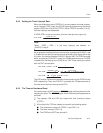
For additional input/output control, ’C2xx devices other than the ’C209 have
pins IO0, IO1, IO2, and IO3, which can be individually configured as inputs or
outputs. These pins are software-controllable with the asynchronous serial
port control register (ASPCR) and the I/O status register (IOSR). For the de-
tails of configuring and using these I/O pins, see subsection 10.3.5,
Using I/O
Pins IO3, IO2, IO1, and IO0
, on page 10-15.


