


How To Use the Instruction Descriptions
7-17
Assembly Language Instructions
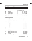
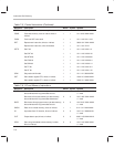
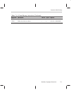
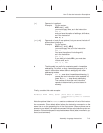
If an instruction requires memory operand(s), the rows in the table indicate the
location(s) of the operand(s), as defined here:
DARAM The operand is in internal dual-access RAM.
SARAM The operand is in internal single-access RAM.
External The operand is in external memory.
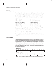
For the RPT mode execution,
n
indicates the number of times a given instruc-
tion is repeated by an RPT instruction. Additional cycles (wait states) can be
generated for program-memory, data-memory, and I/O accesses by the wait-
state generator or by the external READY signal. These additional wait states
are represented in the tables by the following variables:
p Program-memory wait states. Represents the number of additional clock
cycles the device waits for external program memory to respond to a
single access.
d Data-memory wait states. Represents the number of additional clock
cycles the device waits for external data memory to respond to a single
access.
io I/O wait states. Represents the number of additional clock cycles the de-
vice waits for an external I/O device to respond to a single access.
n Number of repetitions (where
n
> 2 to fill the pipeline). Represents the
number of times a repeated instruction is executed.
If there are multiple accesses to one of the spaces, the variable will be preced-
ed by the appropriate integer multiple. For example, two accesses to external
program memory would require 2p wait states. The above variables may also
use the subscripts
src, dst,
and
code
to indicate source, destination, and code,
respectively.
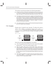
The internal single-access memory on each ’C2xx processor is divided into
2K-word blocks contiguous in address space. All ’C2xx processors support
parallel accesses to these internal single-access RAM blocks. Furthermore,
one single access block allows only one access per cycle. Thus, the processor
can read/write on single-access RAM block while accessing another single-
access RAM block at the same time.
All external reads take at least one machine cycle while all external writes take
at least two machine cycles. However, if an external write is immediately fol-
lowed or preceded by an external read cycle, then the external write requires
three cycles. If the wait state generator or the READY pin is used to add
m
(
m
> 0) wait states to an external access, then external reads require
m
+1
cycles, and external write accesses require
m
+2 cycles. See Section 8.5,
Wait-State Generator
, page 8-14, for the discussion on generating wait states.