


Instruction Set Comparison Table
B-31
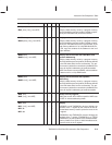
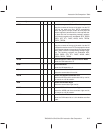
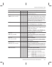
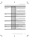
TMS320C1x/C2x/C2xx/C5x Instruction Set Comparison
Syntax
Description5x2xx2x1x
SHM
√ √
Set Hold Mode
Set the HM status bit to 1.
SMMR
dma,
#
lk
SMMR {
ind
}
,
#
lk
[
, next ARP
]
√
√
Store Memory-Mapped Register
Store the memory-mapped register value, pointed at
by the 7 LSBs of the data-memory address, into the
long immediate addressed data-memory location. The
9 MSBs of the data-memory address of the memory-
mapped register are cleared, regardless of the current
value of DP or the upper 9 bits of AR(ARP).
SOVM
√ √ √ √
Set Overflow Mode
Set the OVM status bit to 1; this enables overflow
mode. (The ROVM instruction clears OVM.)
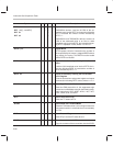
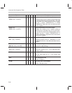
SPAC
√ √ √ √
Subtract P Register From Accumulator
Subtract the contents of the P register from the
contents of the accumulator.
TMS320C2x, TMS320C2xx, and TMS320C5x de-
vices: Before the subtraction, shift the contents of the
P register as specified by the PM status bits.
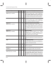
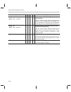
SPH
dma
SPH {
ind
} [
, next ARP
]
√
√
√
√
√
√
Store High P Register
Store the high-order bits of the P register (shifted as
specified by the PM status bits) at the addressed data-
memory location.
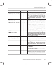
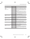
SPL
dma
SPL {
ind
}
[
, next ARP
]
√
√
√
√
√
√
Store Low P Register
Store the low-order bits of the P register (shifted as
specified by the PM status bits) at the addressed data-
memory location.
SPLK #
lk,
dma
SPLK #
lk,
{
ind
}
[
, next ARP
]
√ √
√
Store Parallel Long Immediate
Write a full 16-bit pattern into a memory location. The
parallel logic unit (PLU) supports this bit manipulation
independently of the ALU, so the accumulator is unaf-
fected.
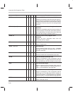
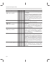
SPM
2-bit constant
√ √ √
Set P Register Output Shift Mode
Copy a 2-bit immediate value into the PM field of ST1.
This controls shifting of the P register as shown below:
PM = 00
2
Multiplier output is not shifted.
PM = 01
2
Multiplier output is left shifted one place
and zero filled.
PM = 10
2
Multiplier output is left shifted four places
and zero filled.
PM = 11
2
Multiplier output is right shifted six places
and sign extended; the LSBs are lost.