


Emulator Cable Pod
E-5
Design Considerations for Using XDS510 Emulator
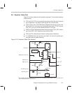
E.3 Emulator Cable Pod
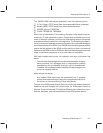
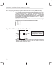
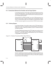
Figure E–2 shows a portion of the emulator cable pod. The functional features
of the pod are:
TDO and TCK_RET can be parallel-terminated inside the pod if required
by the application. By default, these signals are not terminated.
TCK is driven with a 74LVT240 device. Because of the high-current drive
(32-mA I
OL
/I
OH
), this signal can be parallel-terminated. If TCK is tied to
TCK_RET, you can use the parallel terminator in the pod.
TMS and TDI can be generated from the falling edge of TCK_RET, accord-
ing to the IEEE 1149.1 bus slave device timing rules.
TMS and TDI are series-terminated to reduce signal reflections.
A 10.368-MHz test clock source is provided. You can also provide your
own test clock for greater flexibility.
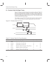
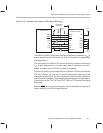
Figure E–2. Emulator Cable Pod Interface
100 Ω
TL7705A
RESIN
270 Ω
JP2
180 Ω
TCK_RET (pin 9)
EMU1 (pin 14)
EMU0 (pin 13)
74AS1034
GND (pins 4,6,8,10,12)
TRST
(pin 2)
TCK (pin 11)
10.368 MHz
33 Ω
33 Ω
TDI (pin 3)
TMS (pin 1)
TDO (pin 7)
74LVT240
180 Ω
JP1
270 Ω
74F175
Q
Q
D
PD(V
CC
) (pin 5)
5 V
5 V
74AS1004
Y
Y
Y
Y
A
†
The emulator pod uses TCK_RET as its clock source for internal synchronization. TCK is provided as an
optional target system test clock source.