


Status Registers ST0 and ST1
3-17
Central Processing Unit
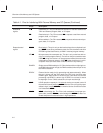
Table 3–2. Bit Fields of Status Registers ST0 and ST1 (Continued)
Name Description
OVM Overflow mode bit. OVM determines how overflows in the CALU are handled. The SETC and
CLRC instructions set and clear this bit, respectively. An LST instruction can also be used to modify
OVM.
OVM = 0 Results overflow normally in the accumulator.
OVM = 1 The accumulator is set to either its most positive or negative value upon encountering
an overflow. (See subsection 3.3.2,
Accumulator
.)
PM Product shift mode. PM determines the amount that the PREG value is shifted on its way to the
CALU or to data memory. Note that the content of the PREG remains unchanged; the value is co-
pied to the product shifter and shifted there. PM is loaded by the SPM and LST instructions. The
PM bits are cleared by reset.
PM = 00 The multiplier’s 32-bit product is passed to the CALU or to data memory with no shift.
PM = 01 The output of the PREG is left shifted one place (with the LSBs zero filled) before be-
ing passed to the CALU or to data memory.
PM = 10 The output of the PREG is left shifted four bits (with the LSBs zero filled) before being
passed to the CALU or to data memory.
PM = 11 This mode produces a right shift of six bits, sign extended.
SXM Sign-extension mode bit. SXM does not affect the basic operation of certain instructions. For
example, the ADDS instruction suppresses sign extension regardless of SXM. This bit is set by the
SETC SXM instruction and cleared by the CLRC SXM instruction, and may be loaded by the LST
instruction. SXM is set to 1 by reset.
SXM = 0 This mode suppresses sign extension.
SXM = 1 This mode produces sign extension on data as it is passed into the accumulator from
the input shifter.
TC Test/control flag bit. The TC bit is set to 1 if a bit tested by BIT or BITT is a 1, if a compare condition
tested by CMPR exists between the current auxiliary register and AR0, or if the exclusive-OR func-
tion of the two MSBs of the accumulator is true when tested by a NORM instruction. The conditional
branch, call, and return instructions can execute based on the condition of the TC bit. The TC bit
is affected by the BIT, BITT, CMPR, LST, and NORM instructions.
XF
XF pin status bit
.
This bit determines the state of the XF pin, which is a general-purpose output
pin. XF is set by the SETC XF instruction and cleared by the CLRC XF instruction. XF can also be
modified with an LST instruction. XF is set to 1 by reset.