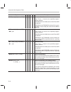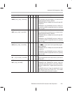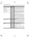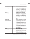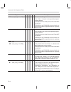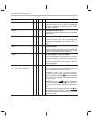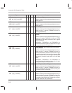
Instruction Set Comparison Table
B-18
Syntax
Description5x2xx2x1x
EINT
√ √ √ √
Enable Interrupts
Enable all interrupts; clear the INTM to 0. Maskable
interrupts are enabled immediately after the EINT
instruction executes.
EXAR
√
Exchange ACCB With ACC
Exchange the contents of the ACC with the contents
of the ACCB.
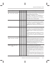
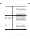
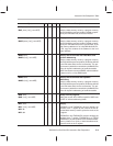
FORT
1-bit constant
√
Format Serial Port Registers
Load the FO with a 0 or a 1. If FO = 0, the registers are
configured to receive/transmit 16-bit words. If FO = 1,
the registers are configured to receive/transmit 8-bit
bytes.
IDLE
√ √ √
Idle Until Interrupt
Forces an executing program to halt execution and
wait until it receives a reset or an interrupt. The device
remains in an idle state until it is interrupted.
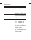
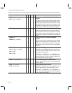
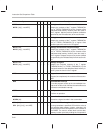
IDLE2
√
Idle Until Interrupt—Low-Power Mode
Removes the functional clock input from the internal
device; this allows for an extremely low-power mode.
The IDLE2 instruction forces an executing program to
halt execution and wait until it receives a reset or
unmasked interrupt.
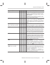
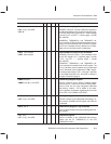
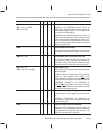
IN
dma, PA
IN {
ind
}
, PA
[
, next ARP
]
√
√
√
√
√
√
√
√
Input Data From Port
Read a 16-bit value from one of the external I/O ports
into the addressed data-memory location.
TMS320C1x devices: This is a 2-cycle instruction.
During the first cycle, the port address is sent to ad-
dress lines A2/PA2–A0/PA0; DEN goes low, strobing
in the data that the addressed peripheral places on
data bus D15–D0.
TMS320C2x devices: The IS
line goes low to indicate
an I/O access, and the STRB
, R/W, and READY tim-
ings are the same as for an external data-memory
read.
TMS320C2xx and TMS320C5x devices: The IS
line
goes low to indicate an I/O access, and the STRB
, RD,
and READY timings are the same as for an external
data-memory read.


