


Interrupts
5-30
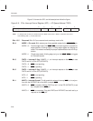
Managing ISRs within ISRs
The ’C2xx hardware stack allows you to have ISRs within ISRs. When consid-
ering nesting ISRs like this, keep the following in mind:
If you want the ISR be interrupted by a maskable interrupt, the ISR must
unmask the interrupt by setting the appropriate IMR bit (and ICR bit, if ap-
plicable) and executing the enable-interrupts instruction (CLRC INTM).
The hardware stack is limited to eight levels. Each time an interrupt is serv-
iced or a subroutine is entered, the return address is pushed onto the hard-
ware stack. This provides a way to return to the previous context after-
wards. The stack contains eight locations, allowing interrupts or subrou-
tines to be nested up to eight levels deep. (One level of the stack is re-
served for debugging, to be used for breakpoint/single-step operations. If
debugging is not used, this extra level is available for internal use.) If your
software requires more than eight stack levels, you can use the POPD and
PSHD instructions to effectively extend the stack into data memory.
If you do not nest ISRs, you can avoid stack overflow. The ’C2xx has a fea-
ture that allows you to prevent unintentional nesting. If an interrupt occurs
during the execution of a CLRC INTM instruction, the device always com-
pletes CLRC INTM as well as the next instruction before the pending inter-
rupt is processed. This ensures that a return instruction that directly fol-
lows CLRC INTM will be executed before an interrupt is processed. The
return instruction will pop the previous return address off the top of the
stack before the new return address is pushed onto the stack.
To allow the CPU to complete the return, interrupts are also blocked after a
RET instruction until at least one instruction at the return address is
executed. Interrupts may be blocked for more than one instruction if the
instruction at the return address requires additional blocking for pipeline
protection.
If you want an ISR to occur
within
the current ISR rather than
after
the cur-
rent ISR, place the CLRC INTM instruction more than one instruction be-
fore the return (RET) instruction.
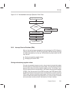
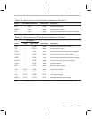
5.6.9 Interrupt Latency
The length of an interrupt latency—the delay between when an interrupt re-
quest is made and when it is serviced—depends on many factors. For exam-
ple, the CPU always completes all instructions in the pipeline before executing
a software vector. This subsection describes the factors that determine mini-
mum latency and then describes factors that may cause additional latency.
The maximum latency is a function of wait states and pipeline protection.