


Connections Between the Emulator and the Target System
E-12
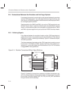
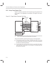
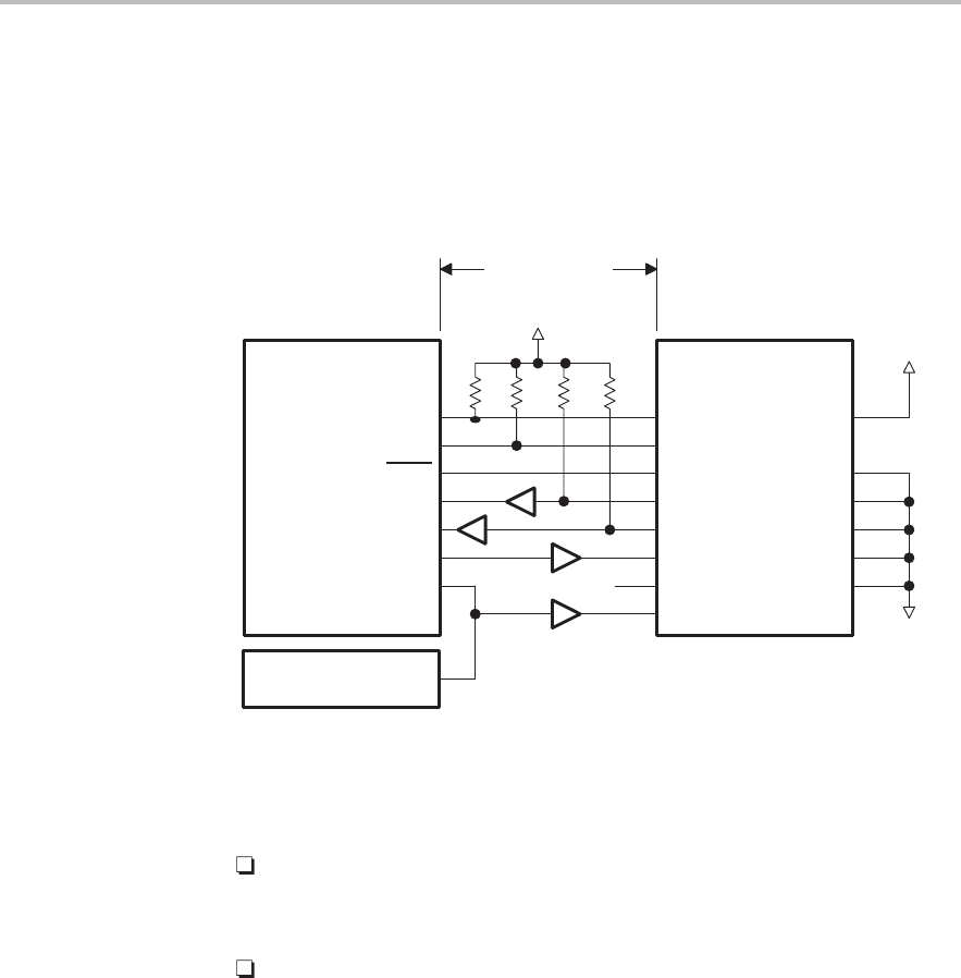
E.6.2 Using a Target-System Clock
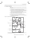
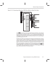
Figure E–6 shows an application with the system test clock generated in the
target system. In this application, the emulator’s TCK signal is left uncon-
nected.
Figure E–6. Target-System-Generated Test Clock
NC
System test clock
V
CC
Emulator header
GND
12
10
8
6
4
5
GND
GND
GND
GND
GND
PD
TCK_RET
TCK
TDO
TDI
TMS
TRST
EMU1
EMU0
9
11
7
3
1
2
14
13
JTAG device
TCK
TDO
TDI
TMS
TRST
EMU1
EMU0
Greater than
6 inches
V
CC
Note: When the TMS and TDI lines are buffered, pullup resistors must be used to hold the buffer
inputs at a known level when the emulator cable is not connected.
There are two benefits in generating the test clock in the target system:
The emulator provides only a single 10.368-MHz test clock. If you allow
the target system to generate your test clock, you can set the frequency
to match your system requirements.
In some cases, you may have other devices in your system that require
a test clock when the emulator is not connected. The system test clock
also serves this purpose.