


Components and Basic Operation
9-3
Synchronous Serial Port
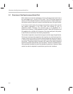
9.2 Components and Basic Operation
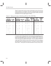
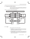
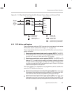
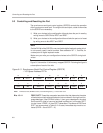
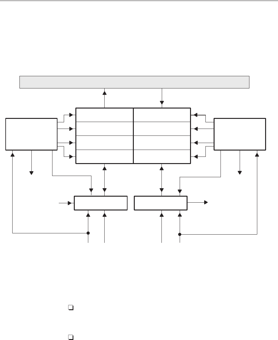
The synchronous serial port has several hard-wired parts, including two FIFO
buffers and six signal pins. Figure 9–1 shows how the components of the syn-
chronous serial port are interconnected.
Figure 9–1. Synchronous Serial Port Block Diagram
SDTR transmit (-3)
RSR XSRDR
DX
FSR FSX CLKXCLKR
SDTR receive (-3)
Receive (-2) Transmit (-2)
Receive (-1) Transmit (-1)
Receive (0) Transmit (0)
RINT XINT
Control
logic
(receive)
Control
logic
(transmit)
Internal data bus
9.2.1 Signals
Serial port operation requires three basic signals:
Clock signal. The clock signal (CLKX/CLKR) is used to control timing dur-
ing the transfer. The timing signal for transmissions can be either gener-
ated internally or taken from an external source.
Frame sync signal. The frame sync signal (FSX/FSR) is used at the start
of a transfer to synchronize the transmit and receive operations. The
frame sync signal for transmissions can be either generated internally or
taken from an external source.