’C209 Interrupts
11-11
TMS320C209
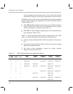
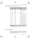
Table 11–4. ’C209 Interrupt Locations and Priorities (Continued)
K
†
Vector
Location
Name Priority Function
15 1Eh INT15 – User-defined software interrupt
16 20h INT16 – User-defined software interrupt
17 22h TRAP – TRAP instruction vector
18 24h NMI 3 Nonmaskable interrupt
19 26h 2 Reserved
20 28h INT20 – User-defined software interrupt
21 2Ah INT21 – User-defined software interrupt
22 2Ch INT22 – User-defined software interrupt
23 2Eh INT23 – User-defined software interrupt
24 30h INT24 – User-defined software interrupt
25 32h INT25 – User-defined software interrupt
26 34h INT26 – User-defined software interrupt
27 36h INT27 – User-defined software interrupt
28 38h INT28 – User-defined software interrupt
29 3Ah INT29 – User-defined software interrupt
30 3Ch INT30 – User-defined software interrupt
31 3Eh INT31 – User-defined software interrupt
†
The K value is the operand used in an INTR instruction that branches to the corresponding
interrupt vector location.
‡
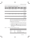
The ’C209 has two pins for triggering a hardware reset: RS
and RS. If either RS is driven low
or RS is driven high, the device will be reset.
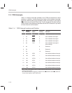
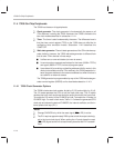
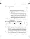
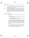
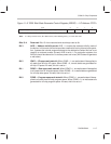
11.3.1 ’C209 Interrupt Registers
As with other ’C2xx devices, the maskable interrupts of the ’C209 are con-
trolled by an interrupt flag register (IFR) and an interrupt mask register (IMR).
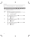
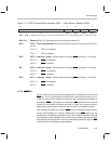
Figure 11–2 shows the IFR and Figure 11–3 shows the IMR. Each of the fig-
ures is followed by descriptions of the bits.


