


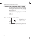

Designing Your Target System’s Emulator Connector (14-Pin Header)
E-3
Design Considerations for Using XDS510 Emulator
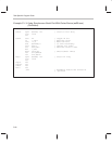
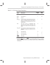
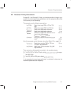
Table E–1. 14-Pin Header Signal Descriptions
Signal Description
Emulator
†
State
Target
†
State
EMU0 Emulation pin 0 I I/O
EMU1 Emulation pin 1 I I/O
GND Ground
PD(V
CC
) Presence detect. Indicates that the emulation
cable is connected and that the target is
powered up. PD should be tied to V
CC
in the
target system.
IO
TCK Test clock. TCK is a 10.368-MHz clock
source from the emulation cable pod. This
signal can be used to drive the system test
clock.
OI
TCK_RET Test clock return. Test clock input to the emu-
lator. May be a buffered or unbuffered version
of TCK.
IO
TDI Test data input O I
TDO Test data output I O
TMS Test mode select O I
TRST
‡
Test reset O I
†
I = input; O = output
‡
Do not use pullup resistors on TRST:
it has an internal pulldown device. In a low-noise
environment, TRST
can be left floating. In a high-noise environment, an additional pulldown
resistor may be needed. (The size of this resistor should be based on electrical current
considerations.)