


Controlling and Resetting the Port
10-14
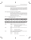
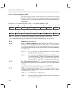
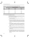
Table 10–2. Common Baud Rates and the Corresponding BRD Values
BRD Value in Hexadecimal
Baud
Rate
CLKOUT1 = 20 MHz
(50 ns)
CLKOUT1 = 28.57 MHz
(35 ns)
CLKOUT1 = 40 MHz
(25 ns)
1200 0411 05CC 0823
2400 0208 02E6 0411
4800 0104 0173 0208
9600 0082 00B9 0104
19200
0041 005C 0082
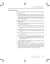
10.3.4 Using Automatic Baud-Rate Detection
The ASP contains auto-baud detection logic, which allows the ASP to lock to
the incoming data rate. The following steps explain the sequence by which the
detection logic could be implemented:
1) Enable auto-baud detection by setting the CAD bit in the ASPCR to 1 and
ADC bit in the IOSR to zero.
2) Receive from a host the ASCII character
A
or
a
as the first character, at
any desired baud rate definable in the BRD register. If the first character
received is
A
or
a
, the serial port will lock to the incoming baud rate (the
rate of the host), and the BRD register will be updated to the incoming baud
rate value.
3) Baud-rate detection is indicated by a TXRXINT interrupt (mapped to vec-
tor location 000Ch) if TXRXINT is unmasked in the interrupt mask register
and is globally enabled by the INTM bit of status register ST0. This inter-
rupt occurs regardless of the values of the DIM, TIM, and RIM bits in the
ASPCR.
4) Following the baud detection interrupt, the ADTR should be read to clear
the
A
or
a
character from the receive buffer. If the ADTR is not cleared, any
subsequent character received will set the OE bit in the IOSR, indicating
an overrun error.
5) Once the baud rate is detected, both the CAD and ADC bits must be
cleared; write 0 to CAD and write 1 to ADC. If CAD is not cleared, the auto
baud-detection logic will try to lock to the incoming character speed. In
addition, for as long as ADC = 1 and CAD = 1, receive interrupts will be
generated.