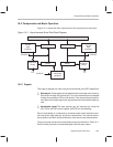
Components and Basic Operation
10-4
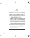
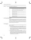
Table 10–1. Asynchronous Serial Port Interface Pins
Pin Name Description
TX
Asynchronous serial port data transmit pin.
Transmits serial data from
the asynchronous serial port transmit shift register (AXSR).
RX
Asynchronous serial port data receive pin.
Receives serial data into the
asynchronous serial port receive shift register (ARSR).
IO0
General purpose I/O pin 0.
Can be used for general purpose I/O or for
handshaking by the UART.
IO1
General purpose I/O pin 1.
Can be used for general purpose I/O or for
handshaking by the UART.
IO2
General purpose I/O pin 2.
Can be used for general purpose I/O or for
handshaking by the UART.
IO3
General purpose I/O pin 3.
Can be used for general purpose I/O or for
handshaking by the UART.
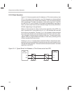
10.2.2 Baud-Rate Generator
The baud-rate generator is a clock generator for the asynchronous serial port.
The output rate of the generator is a fraction of the CLKOUT1 rate and is con-
trolled by a 16-bit register, BRD, that you can read from and write to at I/O ad-
dress FFF7h. For a CLKOUT1 frequency of 40 MHz, the baud-rate generator
can generate baud rates as high as 2.5 megabits/s (250,000 characters/s) and
as low as 38.14 bits/s (3.81 characters/s).
10.2.3 Registers
Four on-chip registers allow you to transmit and receive data and to control the
operation of the port:
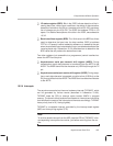
Asynchronous data transmit and receive register (ADTR). The ADTR
is a 16-bit read/write register for transmitting and receiving data. Data writ-
ten to the lower eight bits of the ADTR is transmitted by the asynchronous
serial port. Data received by the port is read from the lower eight bits of the
ADTR. The upper byte is read as zeros. The ADTR is an on-chip register
located at address FFF4h in I/O space.
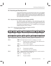
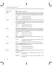
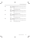
Asynchronous serial port control register (ASPCR). The ASPCR, at
I/O address FFF5h, contains bits for setting port modes, enabling or disab-
ling the automatic baud-rate detection logic, selecting the number of stop
bits, enabling or disabling interrupts, setting the default level on the TX pin,
configuring pins IO3–IO0, and resetting the port. Subsection 10.3.1 gives
a detailed description of the ASPCR.


