


Interrupts
5-25
Program Control
to mask INT3 (prevent the setting of flags FINT3 and INT2/INT3) write a 0 to
MINT3. If INT2/INT3 is not set, the CPU has not received and will not acknowl-
edge the interrupt request.
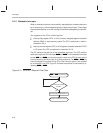
When INT2/INT3 is set, one or both of the interrupts is pending. To differentiate
the occurrences of the two interrupts, your interrupt service routine can test
FINT2 and FINT3 and then branch to the appropriate subroutine. If you want
the interrupt service routine to be executed only in response to one of the inter-
rupts, mask the other interrupt in the ICR. Each of the ICR flag bits, like the IFR
flag bit, can be cleared by writing a 1 to it.
Note:
1) Neither FINT2 nor FINT3 is automatically cleared when the CPU ac-
knowledges the corresponding interrupt. If the application requires the
bit(s) be cleared, the clearing must be done in the interrupt service rou-
tine.
2) Writing 1s to FINT2 and FINT3 will set these bits to 0 but will
not
clear
interrupt requests for INT2
and INT3. To clear requests for INT2 and/or
INT3
, write a 1 to the INT2/INT3 bit of the IFR.
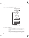
If INT2 or INT3 is unmasked in the ICR, the IFR flag bit will be set regardless
of bit 1 (INT2/INT3) in the IMR. If the IFR flag bit is set, the IMR bit is set, and
the INTM bit is 0 (maskable interrupts are enabled), the CPU will acknowledge
the interrupt. If an interrupt is masked by the IMR and/or the ICR, it will not be
acknowledged, even if INTM = 0.
At reset, all ICR bits are set to zero, which means:
The HOLD/INT1 pin is both negative- and positive-edge sensitive
(MODE = 0).
The FINT2 and FINT3 flag bits are cleared.
INT2 and INT3 are masked.