


’C209 Interrupts
11-10
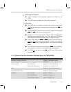
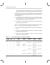
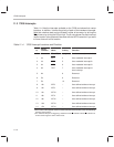
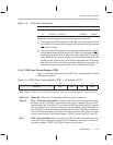
11.3 ’C209 Interrupts
Table 11–4 lists the interrupts available on the ’C209 and shows their vector
locations. In addition, it shows the priority of each of the hardware interrupts.
Note that a device reset can be initiated in either of two ways: by driving the
RS
pin low or by driving the RS pin high. The K value shown for each interrupt
vector location is the operand to be used with the INTR instruction if you want
to force a branch to that location.
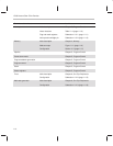
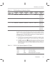
Table 11–4. ’C209 Interrupt Locations and Priorities
K
†
Vector
Location
Name Priority Function
0 0h RS or RS
‡
1 (highest) Hardware reset (nonmaskable)
1 2h INT1 4 User-maskable interrupt #1
2 4h INT2 5 User-maskable interrupt #2
3 6h INT3 6 User-maskable interrupt #3
4 8h TINT 7 User-maskable interrupt #4:
timer interrupt
5 Ah 8 Reserved
6 Ch 9 Reserved
7 Eh 10 Reserved
8 10h INT8 – User-defined software interrupt
9 12h INT9 – User-defined software interrupt
10 14h INT10 – User-defined software interrupt
11 16h INT11 – User-defined software interrupt
12 18h INT12 – User-defined software interrupt
13 1Ah INT13 – User-defined software interrupt
14 1Ch INT14 – User-defined software interrupt
†
The K value is the operand used in an INTR instruction that branches to the corresponding
interrupt vector location.
‡
The ’C209 has two pins for triggering a hardware reset: RS
and RS. If either RS is driven low
or RS is driven high, the device will be reset.