


Hardware Description
3-44 Copyright © 2003-2007 ARM Limited. All rights reserved. ARM DUI 0224F
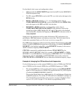
•If CPUCLK is 210MHz the total multiplier ratio of HCLKDIV and
HCLKEXTDIV must be 6.
•The HCLK divider is set to divide by 3 (CFGHCLKDIVSEL[1:0]=
b10
). This
gives an internal AMBA bus and SDRAM clock of 70MHz. See Configuration
control on page 3-7 and Memory characteristics on page 4-15.
• The HCLKEXT divider must be set to divide by 2
(CFGHCLKEXTDIVSEL[2:0]=
b001
) so that the total divider ratio for
HCLKDIV and HCLKEXTDIV is 6. This results in an PLL feedback clock and
external HCLK of 35MHz.
• CPUCLK is 3*2*35MHz (210MHz) as required.
• An MBX clock 70MHz is within the permitted range, so its divider is set to 1
(CFGMBXCLKDIVSEL[1:0]=
b00).
• An SMC of 70MHz is outside the operating frequency range for flash memory, so
the SMC clock divider must be set to 2 (CFGSMCCLKDIVSEL[1:0]=
b01
).
The flash memory in synchronous mode operates at 35MHz
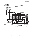
Operating the AHB bridges in asynchronous mode
The following signals control the external part of the AHB bridges if they are operating
in asynchronous mode:
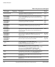
CFGM1ASYNC If HIGH, the external HCLKM1 is selected as the clock for the
external part of bus bridge M1. The signal is controlled by the
value of bit 22 of the SYS_CONFIGDATA2 register. The default
is LOW, the internal clock HCLKEXT is used and the bridge
operates in synchronous mode.
CFGM2ASYNC If HIGH, the external HCLKM2 is selected as the clock for the
external part of bus bridge M2. The signal is controlled by the
value of bit 23 of the SYS_CONFIGDATA2 register. The default
is LOW, the internal clock HCLKEXT is used and the bridge
operates in synchronous mode
CFGSASYNC If HIGH, the external HCLKS is selected as the clock for the
external part of bus bridge S. The signal is controlled by the value
of bit 24 of the SYS_CONFIGDATA2 register. The default is
LOW, the internal clock HCLKEXT is used and the bridge
operates in synchronous mode