


Programmer’s Reference
ARM DUI 0224F Copyright © 2003-2007 ARM Limited. All rights reserved. 4-5
Multi-Port Memory Controller configuration registers Dev. chip -
0x10110000–
0x1011FFFF
64KB
Color LCD Controller Dev. chip PIC 16
0x10120000–
0x1012FFFF
64KB
DMA Controller Dev. chip PIC 17
0x10130000–
0x1013FFFF
64KB
Vectored Interrupt Controller (PIC) Dev. chip -
0x10140000–
0x1014FFFF
64KB
Reserved FPGA -
0x10150000–
0x101CFFFF
64KB
AHB Monitor Interface Dev. chip -
0x101D0000–
0x101DFFFF
64KB
System Controller Dev. chip -
0x101E0000
–
0x101E0FFF
4KB
Watchdog Interface Dev. chip PIC 0
0x101E1000–
0x101E1FFF
4KB
Timer modules 0 and 1 interface
(Timer 1 starts at
0x101E2020
)
Dev. chip PIC 4
0x101E2000–
0x101E2FFF
4KB
Timer modules 2 and 3 interface
(Timer 3 starts at
0x101E3020
)
Dev. chip PIC 5
0x101E3000–
0x101E3FFF
4KB
GPIO Interface (port 0) Dev. chip PIC 6
0x101E4000–
0x101E4FFF
4KB
GPIO Interface (port 1) Dev. chip PIC 7
0x101E5000–
0x101E5FFF
4KB
GPIO Interface (port 2) Dev. chip PIC 8
0x101E6000–
0x101E6FFF
4KB
GPIO Interface (port 3) Dev. chip PIC 9
0x101E7000–
0x101E7FFF
4KB
Real Time Clock Interface Dev. chip PIC 10
0x101E8000–
0x101E8FFF
4KB
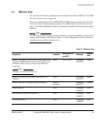
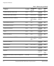
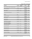
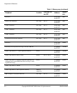
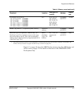
Table 4-1 Memory map (continued)
Peripheral Location
Interrupt
a
PIC
and SIC
Address
Region
size