


Signal Descriptions
A-40 Copyright © 2003-2007 ARM Limited. All rights reserved. ARM DUI 0224F
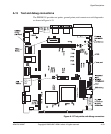
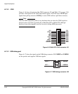
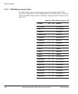
A.13.7 FPGA debug connector pinout
The FPGA debug connector contains address and decode signals that the FPGA
generates to communicate with the USB and Ethernet controllers. Table A-16 lists the
pinout of the FPGA debug connector. The Mictor connector is shown in Figure A-19 on
page A-38.
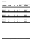
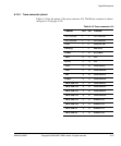
Table A-16 FPGA debug connector J39
Channel Pin Pin Channel
Not connected 1 2 Not connected
GND 3 4 Not connected
ETHWnR 56ETHnLDEV
ETHnRDYRTN 78ETHARDY
USBnRESET 910ETHnDATACS
ETHnSRDY 11 12 ETHAEN
USBDACK0 13 14 ETHnADS
USBEOT0 15 16 ETHnCYCLE
ETHA15 17 18 USBnCS
ETHA14 19 20 USBnWR
ETHA13 21 22 USBnRD
ETHA9 23 24 Not connected
USBETHA8 25 26 Not connected
USBETHA7 27 28 Not connected
USBETHA6 29 30 F2LSPARE4
USBETHA5 31 32 F2LSPARE3
USBETHA4 33 34 F2LSPARE2
USBETHA3 35 36 F2LSPARE1
USBETHA2 37 38 F2LSPARE0