


CLCD Display and Adaptor Board
C-12 Copyright © 2003-2007 ARM Limited. All rights reserved. ARM DUI 0224F
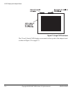
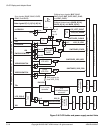
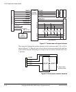
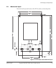
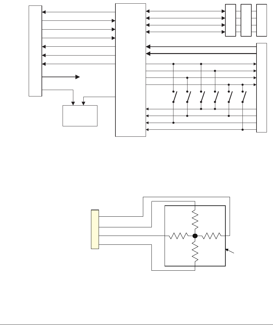
Figure C-7 Touchscreen and keypad interface
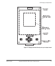
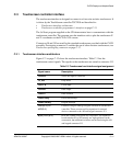
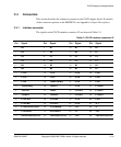
The connection between the resistive elements of the touchscreen and J3, J8, or J10 is
shown in Figure C-8. When the pen is down, the two resistive elements touch and form
a four-resistor network. Measuring the voltages at the two dividers indicates the X and
Y positions.
Figure C-8 Touchscreen resistive elements
TSMISO
TSSCLK
TSMOSI
J3
TSnSS
TSnDAV
X_NEG
X_POS
Y_NEG
Y_POS
J13 A/D and keypad connector
TSnKPADIRQ
TSnPENIRQ
VBAT[2:1]
AUX[2:1]
RGB and sync
to display
Interface socket
Touch
screen
controller
Power
control
VDD POS
Power shutdown signals
FB2 (DA out)
S3
R1
C3
C2
C1
C4
R2
R3
R4
S4 S5 S6 S7
S8
User switches
J8
J10
<B326
<B1(*
;B326
;B1(*
7RXFKVFUHHQ
UHVLVWLYHVKHHWV
&RQQHFWRU