


Signal Descriptions
ARM DUI 0224F Copyright © 2003-2007 ARM Limited. All rights reserved. A-9
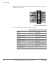
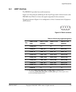
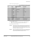
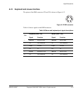
Table A-5 lists the signal assignments.
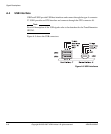
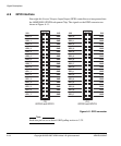
There are two MMC connectors.
• MMC 0 is J21 on the top side of the board (replace x with 0 in Table A-5)
• MMC 1 is J22 on the bottom side (replace x with 1 in Table A-5).
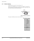
Insert and remove the card as follows:
Insertion For the connector on the top of the board, insert the card into the socket
with the contacts face down. For the connector on the bottom of the
board, insert the card into the socket with the contacts face up as viewed
from the top of the board. Cards are normally labeled on the top surface
with an arrow to indicate correct insertion.
Removal Remove the card by gently pressing it into the socket. It springs back and
can be removed. Removing the card in this way ensures that the card
detection switches within the socket operate correctly.
Table A-5 Multimedia Card interface signals
Pin Signal
Function SD widebus
mode
Function MCI
1 MCIxDATA3 Data Chip select
2 MCIxCMD Command/response Data in
3 GND Ground Ground
4 MCIVDDx Supply voltage Supply voltage
5 MCICLKx Clock Clock
6 GND Ground Ground
7 MCIxDATA0 Data 0 Data out
8 MCIxDATA1 Data 1 NC
9 MCIxDATA2 Data 2 NC
10 (DET A) CARDINx Card insertion detect Card insertion detect
11 (DET B) WPROTx Write protect status Write protect status