Signal Descriptions
A-38 Copyright © 2003-2007 ARM Limited. All rights reserved. ARM DUI 0224F
A.13.5 Embedded logic analyzer
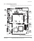
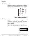
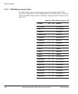
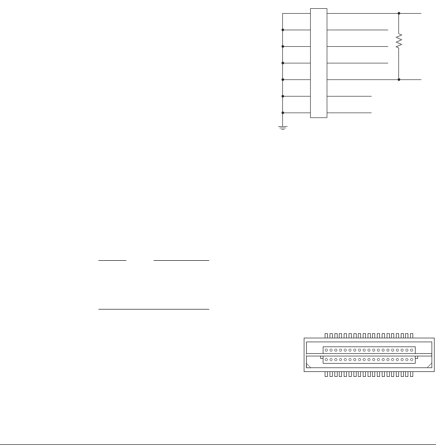
Figure A-18 shows the signals on the embedded logic analyzer connector J33. Use an
embedded logic analyzer to debug FPGA designs and software at the same time. For
more information, see the documentation supplied with your analyzer. (The ChipScope
product is described on the Xilinx web site at
www.xilinx.com
.)
Figure A-18 Embedded logic analyzer connector J33
A.13.6 AHB monitor
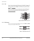
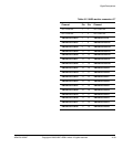
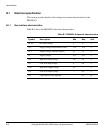
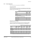
An AHB bus monitor, or logic analyzer, can be connected to the AHB monitor port on
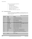
the PB926EJ-S using a high-density AMP Mictor connector J17. The connector carries
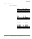
33 signals and 1 clock or qualifier. Figure A-19 shows a connector and the identification
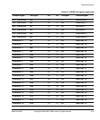
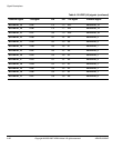
of pin 1. Table A-15 on page A-39 lists the pinout of the connector.
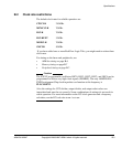
Note
Agilent (formerly HP) and Tektronix label these connectors differently, but the
assignments of signals to physical pins is appropriate for both systems and pin 1 is
always in the same place. The figure is labelled according to the Agilent pin assignment.
Figure A-19 AMP Mictor connector
8 ILA_TDO
SSP connector
3
11
4 ILA_TMS
6 ILATCK
2 3V3
5
10 ILATDI
12 NC
14 NC
7
9
13
10K
1
2
37
38


