


Getting Started
2-4 Copyright © 2003-2007 ARM Limited. All rights reserved. ARM DUI 0224F
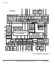
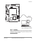
Configuration switches S1-1 to S1-8 are not normally changed from their factory
default positions listed in Table 2-2. For more information on configuration switch S1,
see Configuration control on page 3-7.
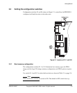
Note
For information on other configuration links see Test, configuration, and debug
interfaces on page 3-94. For the function of the status LEDs see LED Indicators on
page 2-5,
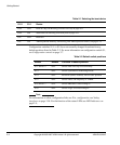
Table 2-1 Selecting the boot device
S1-2 S1-1 Device
OFF OFF Disk on Chip, see Booting from Disk on Chip on page 4-11
OFF ON NOR flash, see Booting from NOR flash on page 4-12
ON OFF Reserved
ON ON AHB expansion memory, see Booting from AHB expansion memory on page 4-14
Table 2-2 Default switch positions
Switch Default Function in default position
S1-1 and S1-2 OFF Selects Disk-on-Chip as boot memory
S1-3 OFF Selects synchronous AHB bridge mode.
S1-4 OFF Reserved (SSMC enabled), leave in OFF position
S1-5 OFF Selects OSCCLK frequency of 35MHz.
S1-6 and S1-7 OFF Selects PB926EJ-S FPGA image 0
S1-8 OFF Selects Logic Tile FPGA image 0