


Programmer’s Reference
4-82 Copyright © 2003-2007 ARM Limited. All rights reserved. ARM DUI 0224F
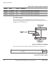
Configuring the PCI interface
To configure a PCI card in the expansion bus, first find the memory location that maps
the PB926EJ-S into the system:
1. Scan addresses
0x41000000 + (n<<11)
to locate the PCI slot holding the
PB926EJ-S. The slot range for
n
is 11 to 31. If you are using the horizontal slot
on the PCI expansion backplane,
n
is 29.
2. Write the value of
n
that indicates the slot position into the PCI_SELFID register.
3. Set bit 2 of the Command/Status Register (at offset
+0x04
) to enable the
PB926EJ-S to be initiator on the system. This enables initiator transfers.
4. Because the PCI_SELFID register now holds the slot number for the PB926EJ-S,
scanning the normal configuration space at
0x42000000
reveals all PCI cards in the
backplane.
Perform normal configuration cycles on other slot positions to see what else is on
the bus. Instead of the self config area at
0x41000000
, use memory locations in
Config area
0x42000000 + (n<<11)
, where
n
is 11 to 31. That is, scan:
0x42005800
,
0x42006000
,
0x42006800
, and so on to
0x4200f800
.
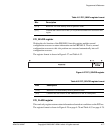
5. The accesses return
0xFFFFFFFF
if the slot is empty, or the device and vendor id for
card present. (For the PB926EJ-S, the device/vendor id is
0x030010EE
.)
If a card is present, read the base address registers to determine how much and
what type of memory is required by each of target boards found in the system.
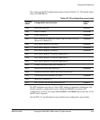
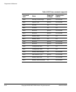
6. Write to the base address registers in the header table to setup the PCI memory
map and tell each target the PCI memory addresses they should respond to (see
Table 4-57 on page 4-81).
7. Set the PCI control registers at
0x10001000
appropriately so an access to one of the
three memory regions causes a PCI access to the correct PCI memory location.
Note
An example of PCI scanning and configuration is provided as an example on the CD.