


Programmer’s Reference
4-10 Copyright © 2003-2007 ARM Limited. All rights reserved. ARM DUI 0224F
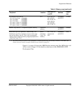
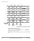
Configuration switch S1 modifies the memory map of static memory at reset as listed
in Table 4-2. S1-1 controls BOOTCSSEL0 and S1-2 controls BOOTCSSEL1. If a
switch is ON, the corresponding BOOTCSSEL signal is HIGH.
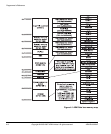
A simplified version of the remap logic is shown in Figure 3-14 on page 3-28.
Removing boot remapping and enabling SDRAM at 0x0
The ARM926EJ-S PXP Development Chip begins executing at
0x0
after a reset. But
because DEVCHIP REMAP and FPGA_REMAP are active at reset, the remapping
logic uses causes boot instructions to be fetched from non-volatile static memory.
The boot code must perform the following actions on reset to remove the remapping and
enable SDRAM at
0x0
:
1. At reset, the remap signals are both high, therefore static memory is remapped to
address
0x0
. Perform any critical CPU initialization at this time.
Ensure that you do not access SDRAM at this point as it has not been initialized.
2. For Disk-on-Chip (nDOCCS) or NOR flash (nNORCS), jump to a location in
the range
0x34000000–0x37FFFFFF
. Jumping out of the range
0x000000000–0x03FFFFFF
means that the remapped memory at
0x0
is no longer
needed and can be unmapped.
The code jumps to
0x34000000–0x37FFFFFF
rather than the physical location of the
boot memory because the boot code does not know which physical memory
device it is located in and because the control registers for the other static memory
device selects are not installed.
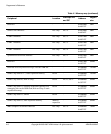
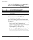
Table 4-2 Selecting the boot device
S1-2 S1-1 Device
OFF OFF Disk on Chip, see Booting from Disk on Chip on page 4-11
OFF ON NOR flash, see Booting from NOR flash on page 4-12
ON OFF Reserved
ON ON AHB expansion memory on a RealView Logic Tile, see Booting from AHB expansion
memory on page 4-14