


CLCD Display and Adaptor Board
ARM DUI 0224F Copyright © 2003-2007 ARM Limited. All rights reserved. C-9
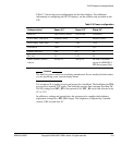
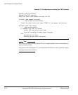
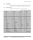
Table C-2 shows the power configuration for the three displays. For additional
information on configuring the CLCD displays, see the selftest code provided on the
CD.
Caution
The links for power control are set during manufacture. Do not modify the links unless
you are producing a new custom display board.
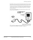
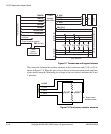
Use connector J4 to supply power to an inverter for a backlight. The backlight pins VIN
are provide a nominal 12V supply. The backlight inverter must consume less than 5W.
The I/O voltage level INV_IO is also present on J4. INV_IO can be link selected to be
5V or 3.3V.
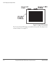
In addition to voltage and ground pins, the connector also supplies the brightness
adjustment voltage (0 to INV_IO voltage). The brightness is adjusted by a variable
resistor, VR4, located near J4.
Table C-2 Power configuration
Voltage control Epson 2.2
”
Sanyo 3.8
”
Sharp 8.4
”
Buffer IO SWITCHED_FIXED CLPOWER CLPOWER
SWITCHED_VDD_POS Software control 15V Software control
SWITCHED_VDD_NEG –10V –10V –10V
CLPOWER 2.85V 3.3V 3.3V
FIXED_SWITCH 1.8V 5V 5V
INV_IO 5V 3.3V 5V
Buffer enabled (software
control)
Always on Always on Set from CLPOWER
register in ARM926EJ-S
PXP Development Chip