


Programmer’s Reference
ARM DUI 0224F Copyright © 2003-2007 ARM Limited. All rights reserved. 4-61
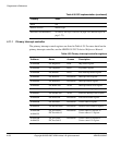
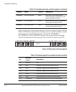
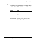
4.11.2 Secondary interrupt controller
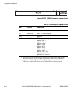
The register map for the secondary interrupt controller is shown in Table 4-41.
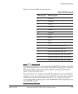
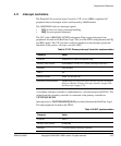
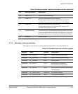
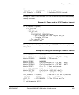
[4] Timer 0 or 1 Timers on development chip
[3] Comms TX Debug communications transmit interrupt.
This interrupt indicates that the communications channel is
available for the processor to pass messages to the debugger.
[2] Comms RX Debug communications receive interrupt.
This interrupt indicates to the processor that messages are
available for the processor to read.
[1] Software interrupt Software interrupt. Enabling and disabling the software interrupt
is done with the Enable Set and Enable Clear Registers. Triggering
the interrupt however, is done from the Soft Interrupt Set register.
[0] Watchdog Watchdog timer
a. The VICINTSOURCEx signals are external to the ARM926EJ-S PXP Development Chip.
Table 4-40 Interrupt signals to primary interrupt controller (continued)
Bit
Interrupt source
a
Description
Table 4-41 Secondary interrupt controller registers
Address Name Access Description
0x10003000
SIC_STATUS Read Status of interrupt (after mask)
0x10003004
SIC_RAWSTAT Read Status of interrupt (before mask)
0x10003008
SIC_ENABLE Read Interrupt mask
0x10003008
SIC_ENSET Write Set bits HIGH to enable the
corresponding interrupt signals
0x1000300C
SIC_ENCLR Write Set bits HIGH to mask the corresponding
interrupt signals
0x10003010
SIC_SOFTINTSET Read/write Set software interrupt
0x10003014
SIC_SOFTINTCLR Write Clear software interrupt