


Programmer’s Reference
ARM DUI 0224F Copyright © 2003-2007 ARM Limited. All rights reserved. 4-53
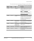
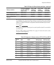
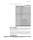
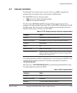
Table 4-33 shows the DMA channel allocation.
Note
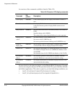
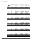
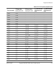
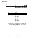
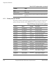
The three DMA channels 0, 1, and 2 are connected to the FPGA, but there are more than
three FPGA peripherals that can use DMA. Three DMA mapping registers control the
FPGA device that has access to the channels. Table 4-34 on page 4-54 shows the
register format and possible values.
Because channels 0,1, or 2 might be used by FPGA peripherals. It is recommended that,
if possible, you use only channels 3,4, and 5 for RealView Logic Tiles. If user-supplied
peripherals in a tile also requires DMA channels 0,1, or 2, you must program the
corresponding DMA mapping register so that the PB926EJ-S FPGA peripherals do not
drive that DMA channel.
Table 4-33 DMA channels
DMA channel DMA Requester
15 UART0 Tx
14 UART0 Rx
13 UART1 Tx
12 UART1 Rx
11 UART2 Tx
10 UART2 Rx
9 SSP Tx
8 SSP Rx
7SCI Tx
6SCI Rx
5 I/O device in RealView Logic Tile
4 I/O device in RealView Logic Tile
3 I/O device in RealView Logic Tile
2 I/O device in RealView Logic Tile or FPGA
1 I/O device in RealView Logic Tile or FPGA
0 I/O device in RealView Logic Tile or FPGA