


Signal Descriptions
ARM DUI 0224F Copyright © 2003-2007 ARM Limited. All rights reserved. A-17
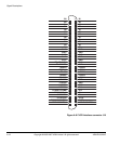
A.12 RealView Logic Tile header connectors
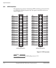
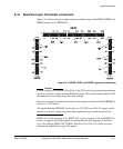
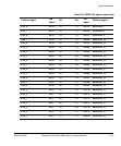
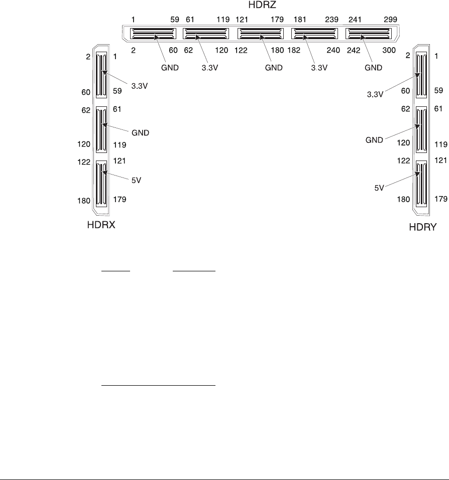
Figure A-14 shows the pin numbers and power-blade usage of the HDRX, HDRY, and
HDRZ headers on the PB926EJ-S.
Figure A-14 HDRX, HDRY, and HDRZ (upper) pin numbering
Caution
The I/O voltage on some pins of RealView Logic Tiles can be programmed by changing
resistors on the tile. Signals between RealView Logic Tiles can be altered safely if both
the sending and receiving tile use the same voltage.
However, all signals from the tile mounted on the expansion headers and the PB926EJ-S
must use 3.3V I/O levels.
All signals from the PB926EJ-S to the tile use 3.3V I/O levels. The 5V supply on the
headers is to power voltage converters that might be present on the expansion tile.
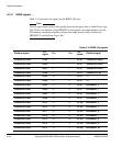
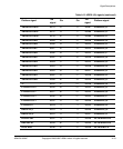
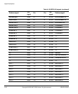
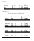
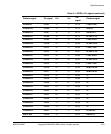
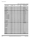
HDRX (J9) signals on page A-18, HDRY (J12) signals on page A-22, and HDRZ (J8)
signals on page A-26 list the signals on each header pin. See Appendix F RealView
Logic Tile and the ARM LT-XC2V4000+ RealView Logic Tile User Guide for more
information on RealView Logic Tile signals.