Signal Descriptions
A-8 Copyright © 2003-2007 ARM Limited. All rights reserved. ARM DUI 0224F
A.6 MMC and SD flash card interface
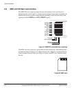
The MMC/SD card sockets provides nine pins that connect to the card when it is
inserted into the socket. Figure A-7 shows the pin numbering and signal assignment. In
addition, the socket contains switches that are operated by card insertion and provide
signaling on the CARDINx and MCI_WPROT signals.
Figure A-7 MMC/SD card socket pin numbering
The MMC card uses seven pins, and the SD card uses all nine pins. The additional pins
are located as shown in Figure A-7 with pin 9 next to pin 1 and pins 7 and 8 spaced more
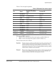
closely together than the other pins. Figure A-8 shows an MCI card, with the contacts
face up.
Figure A-8 MMC card
DATA3
CMD
Ground
VDD
Clock
DATA0
DATA1
DATA2
Card in
Write protect
8
7
6
5
4
3
2
1
9
Ground
Ground
Ground
1234
5
6
7


