


Programmer’s Reference
ARM DUI 0224F Copyright © 2003-2007 ARM Limited. All rights reserved. 4-81
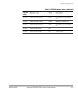
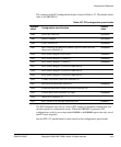
The contents of the PCI configuration header is listed in Table 4-57. The default values
refer to the PB926EJ-S.
The PCI backplane uses the top 3 bits of PCI address to determine whether that slot
should respond to configuration cycles. When the PB926EJ-S generates PCI
configuration cycles by accessing the
0x41000000
or
0x42000000
region, the only one of
the PCI cards responds.
See the PCI v2.2 specification for more detail on the configuration space header.
Table 4-57 PCI configuration space header
Address
offset
Configuration word function
Default
value
+0x00
Device ID Vendor ID
0x030010EE
+0x04
Status Command
0x02200000
+0x08
Class Code Rev ID
0x0B400000
+0x0C
BIST (Reserved in PB926EJ-S) Header Type Lat. timer Line Size
(Reserved in PB926EJ-S)
0x00000000
+0x10
Base Address Register 0 (I/O bytes)
0x00000001
+0x14
Base Address Register 1 (memory)
0x00000008
+0x18
Base Address Register 2 (memory)
0x00000008
+0x1C
Base Address Register 3 (reserved in PB926EJ-S) -
+0x20
Base Address Register 4 (reserved in PB926EJ-S) -
+0x24
Base Address Register 5 (reserved in PB926EJ-S) -
+0x28
Cardbus CIS Pointer (reserved in PB926EJ-S) -
+0x2C
Subsystem ID Subsystem Vendor ID
0x00000000
+0x30
Expansion ROM Base Address (Reserved in PB926EJ-S) -
+0x34
Unused (Reserved in PB926EJ-S) CapPtr
0x00000000
+0x38
(Reserved in PB926EJ-S) -
+0x3C
Max_Lat Min_Gnt Interrupt PinInterrupt line
0x000001FF