


Hardware Description
ARM DUI 0224F Copyright © 2003-2007 ARM Limited. All rights reserved. 3-63
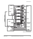
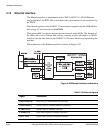
See Color LCD Controller, CLCDC on page 4-47 and the ARM926EJ-S Development
Chip Reference Manual for interface details.
The ARM926EJ-S PXP Development Chip also contains a MOVE video encoding
coprocessor and a MBX graphics accelerator, see the ARM MOVE Coprocessor
Technical Reference Manual and ARM MBX HR-S Graphics Core Technical Reference
Manual for details.
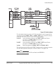
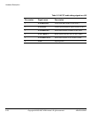
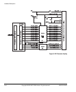
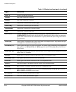
Table 3-14 Display interface signals
Signal Description
CLD[23:0] LCD panel data. This is the digital RGB signals and synchronization signals.
CLCP LCD panel clock to or from the RealView Logic Tile. A buffered version of this signal is output to
the CLCD adaptor board as BUF_CLCP. This signal can also be driven to the RealView Logic
Tile on LT_CLCP.
CLLP Line synchronization pulse (STN)/horizontal synchronization pulse (TFT) to or from the
RealView Logic Tile. A buffered version of this signal is output to the CLCD adaptor board as
BUF_CLLP. This signal can also be driven to the RealView Logic Tile on LT_CLLP.
CLFP Frame pulse (STN)/vertical synchronization pulse (TFT) to or from the RealView Logic Tile. A
buffered version of this signal is output to CLCD adaptor board as BUF_CLFP. This signal can
also be driven to the RealView Logic Tile on LT_CLFP.
CLAC STN AC bias drive or TFT data enable output to or from the RealView Logic Tile. A buffered
version of this signal is output to the CLCD adaptor board as BUF_CLAC. This signal can also
be driven to the RealView Logic Tile on LT_CLAC.
CLLE Line end signal to or from the RealView Logic Tile. A buffered version of this signal is output to
the CLCD adaptor board as BUF_CLLE. This signal can also be driven to the RealView Logic
Tile on LT_CLLE.
CLPOWER LCD panel power enable. Depending on the link settings on the CLCD adaptor board, this signal
can be used to turn off power to the display.
B[7:0] Blue output signals to D/A converter and to or from the RealView Logic Tile. A buffered version
of these signals are output to the CLCD adaptor board as BUF_B[7:0].
G[7:0] Green output signals to D/A converter and to or from the RealView Logic Tile. A buffered version
of these signals are output to the CLCD adaptor board as BUF_G[7:0].
R[7:0] Red output signals to D/A converter and to or from the RealView Logic Tile. A buffered version
of these signals are output to the CLCD adaptor board as BUF_R[7:0].
RED, GREEN,
BLUE
Analog output from D/A converter for red, green, and blue signals to VGA connector.